About Doors
Doors can be added in plan, elevation, section or a 3D view. Doors are loadable families, which means that the family of the door (sizes, shapes, design) can be customized and placed in the library to later load them in your project.
Doors are dependent elements on their host which is usually a wall. Like in real life, a door cannot be placed if there is no wall on site. Similarly, in Revit, a door cannot be placed without a wall.
Tutorial Objective:
In this tutorial, you will learn,
- To load a family into the project
- To customize the door sizes and create new door types
- To place a door in the project
- To adjust the position of the door using permanent dimension and equality constraint
- Use temporary dimensions to adjust the position of the door
- Use Move Tool to adjust the position of the door
- Use Align tool to adjust the position of the door
Sample Problem:
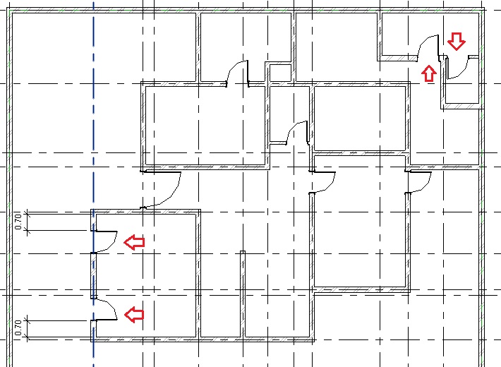
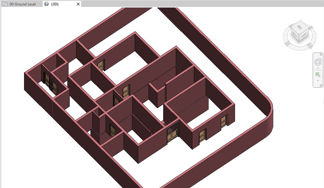
- Add doors of following types in the Ground Floor layout as shown below:
- Door_Single Panel: 0.9 x 2.1 m (all doors except the entrance door)
- Door_Entrance: 1.50 x 2.63 m (at the entrance of the residence)

Sample Files required for this tutorial:
If you do not have the following files, please download them from here.
- “TutorialDoors_Input_LearningRevitOnline.rvt”
- Door Family files: “Door_Single Panel.rfa” and “Door_Entrance.rfa”
Solution:
- Open tutorial file ‘TutorialDoors_Input_LearningRevitOnline.rvt’ in Revit. This project file already contains walls in the Basement and Ground Floor levels.
- Navigate to the floor plan of “00 Ground Level”.
- Doors are loadable families which means we will first need to load the family of the doors from the library (if it is not already loaded in your project).
-
To load a family into the project:
- Click Insert tab -> Load from Library panel -> Load Family
- Navigate to the folder where you have downloaded and saved the Door_Single Panel.rfa (If you do not have this file yet, please download it from here).
- Note: By default, Revit will navigate to the library where default Autodesk families are stored. If you do not find this path when you need it, try to locate it on your PC at : %ALLUSERSPROFILE%\Autodesk\RVT 2019\Libraries (If you cannot still find the location of your family library, please see this Video Tutorial: Locating your family folder )

- Note: By default, Revit will navigate to the library where default Autodesk families are stored. If you do not find this path when you need it, try to locate it on your PC at : %ALLUSERSPROFILE%\Autodesk\RVT 2019\Libraries (If you cannot still find the location of your family library, please see this Video Tutorial: Locating your family folder )
- Select the file and Click Open.
- The family has been loaded into the project.
- Now, before we add the doors into our model, we must create the Door types with the specific sizes as required for our project.
-
To customize the door sizes and create new door types:
- Click Architecture tab -> Build panel -> Door
- Alternatively, use “DR”as keyboard shortcut.
- From the type selector, select any of the types available for Door_Single Panel family.
- From the properties, select Edit Type to access Type properties palette.
- Click Duplicate to create a new Door Type. In the Name dialog box, give a new name to the door type “Door_Single Panel_0.9 x 2.1”

- Click Ok to the Name dialog box.
- Now, change the parameters Width to 0.9m value and Height to 2.1m value.
- Click OK to the Type Properties dialog box.

- A new Door type has been created.
- Click Esc to end the Door tool.
- Click Architecture tab -> Build panel -> Door
- Repeat Step 4 to load the family Door_Entrance.rfa (If you do not have this file yet, please download it from here).
- Repeat Step 6 to create a new door type for the Door_Entrance.rfa family. Name the new Door type as “Door_Entrance_1.50 x 2.63” and change the size parameters to width = 1.50m and height = 2.63m

- Now, as all the door types are prepared, we can begin to place doors in the model.
- TIP: If you are not sure of which type of door types to place in your design, you can always begin by placing doors of any particular type and then later change the door type to a specific one when you have the information. This can be done by simply selecting the door in the model and changing its type from the type selector.
-
To place a door in the project:
- Click Architecture tab -> Build panel -> Door
- Alternatively, use “DR”as keyboard shortcut.
- Select the Door type Door_Entrance_1.50 x 2.63 from the type selector.
- In the drawing area, move your cursor towards the wall where you would like to place the door (between Grid C4-C5 as shown below). Listening dimensions (in blue) will appear to support you to find the position on the wall.
- TIP: Hover your cursor towards the direction where you would like to set the orientation of the door. The door will flip accordingly. You can also press the Spacebar to flip the door hand from left to right while placing the door in plan view.

- TIP: Hover your cursor towards the direction where you would like to set the orientation of the door. The door will flip accordingly. You can also press the Spacebar to flip the door hand from left to right while placing the door in plan view.
- Click on the wall to place the door. Do not worry about the exact positioning of the door or orientation at this moment. You can adjust this after you have placed the door.
- Click Esc twice to end the Door tool.
- Note that after placing the door, Revit has made an appropriate opening in the wall automatically.
- Click Architecture tab -> Build panel -> Door
- Click on the door that you have placed. Flip arrows will appear in the middle of the door. Click on the flip arrows if you wish to change the orientation of the door.
- We would like to position the door exactly in the center of the two neighboring walls as shown in Fig 1. To do this, the best way is to use permanent dimension and equality constraint.
-
To adjust the position of an element using permanent dimension and equality constraint:
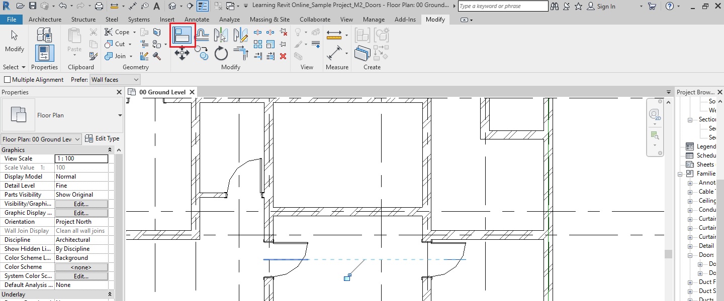
- Go to Annotate tab -> Dimension panel -> Aligned
- On the options bar, select Wall Center line and Pick: Individual References
- Click the center line of the wall on Grid 4.
- Click on the center of the Door.
- Click the center line of the wall on Grid 5.
- Click on empty space to place the dimension.
- Click Esc twice to end the Dimension tool.
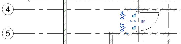
- Select the dimension that you have placed.
- There is a small “EQ” sign besides the dimension. Click on this EQ sign.
- The dimension values will change and display text EQ instead of the values. This shows that the dimensions from the wall center line to the center of the door on both sides have been constrained to be equal. The position of the door has adjusted accordingly. If the wall moves, the door will also move with it to maintain the equal distance to its center.

- Click Esc to deselect the dimension.
- If you delete the dimension, a warning sign will be displayed explaining that equality constraint between the elements will be maintained even when the dimension is deleted. Say OK if you wish to do so. If you do not want the equality constraint to be maintained, then select Unconstrain.

- Now, repeat step 10 to place the door type “Door_Single Panel_0.9 x 2.1” near Grid F-2 as shown below.

-
Use temporary dimensions to adjust the position of the door:
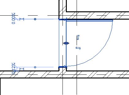
- Select the door after placing it. Temporary dimensions will appear. Click on the temporary dimension’s value and change it to 0.7m as shown below to place the door 0.7m away from the wall on Grid G.
- Drag a control for the witness line (the blue dots shown in the image) to a different reference, if needed (for ex: from center of the wall to face of the wall)
- Alternatively, right-click the witness line control, and click Move Witness Line. You can then move the witness line to a new reference.
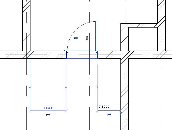
- Select the door after placing it. Temporary dimensions will appear. Click on the temporary dimension’s value and change it to 0.7m as shown below to place the door 0.7m away from the wall on Grid G.
- Now, repeat step 10 to place the door type “Door_Single Panel_0.9 x 2.1” as shown below.

- Now, for this door, we would like to position the right door frame attached to the right wall. To do this, the best way would be to use Move tool.
-
Use Move Tool to adjust the position of the door:
- Go to Modify tab -> Modify panel -> Move
- Alternatively, use “MV” as a keyboard shortcut.
- Click on the edge of the right door frame as the base point.
- Click on the edge of the wall where the door frame needs to be moved.
- Go to Modify tab -> Modify panel -> Move


After the door has been moved, click Esc to end the Move tool.

Use Align tool to adjust the position of the door:
- Go to Modify tab -> Modify panel -> Align
- Alternatively, use “AL” as a keyboard shortcut.
- Click on the center line of the door on Grid K to set it as a reference.
- Now, click on the center line of the door on Grid I to align with the reference.
- Both doors are now aligned with each other.
- Click Esc to end the Align tool.
More References:
- After placing the door, if you would like to move it to another wall, use ‘pick new host’ tool to move the door.
- If you would like to create your own custom family for the door, it is advised that you first familiarize yourself with basic family editing tools covered in later sections of this course. However, if you are already familiar with them, you can create a custom door as guided by this Video Tutorial: How to create a door family presented by Brett Grinkmeyer.

One thought on “Tutorial: Doors”