About Roof
You can create a roof in Revit using mainly the “Roof by Footprint” and “Roof by Extrusion” methods. Different shapes of roofs can also be developed using combination of both of these methods. To create dynamic shapes of roofs, “Roof by Face” method along with Massing can be used.Tutorial Objective:
In this tutorial, we will be learning the ‘Roof by Extrusion’ approach. To learn more about other methods to create Roof, use the resources here. In this tutorial, you will learn,Sample Problem:
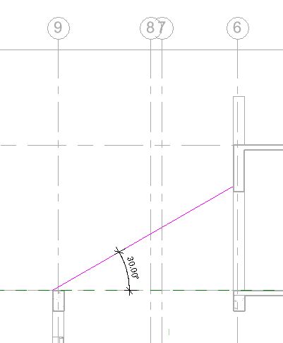
Create a 100mm thick concrete roof at 30 degree angle between Grid 6-9 and Grid E-F in the sample tutorial project as shown in Fig 1 and 2 below.
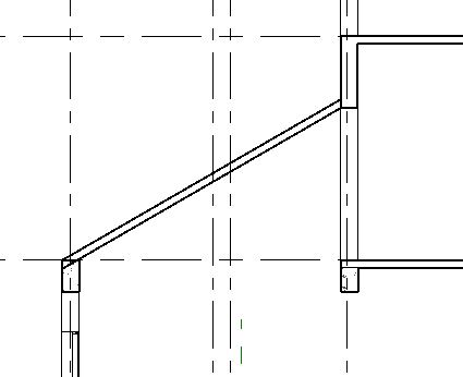
Fig 1. Sloped Roof in the sample tutorial project

Fig 2. Sloped Roof in the sample tutorial project
- “TutorialRoof_Input_LearningRevitOnline.rvt”
Solution:
- The tutorial file “TutorialRoof_Input_LearningRevitOnline.rvt” already contains basic model of the building.
- Navigate to the floor plan of “02 Second Floor Level”.
- To create a the profile of the roof as shown in Fig 1 above, we will use ‘Roof By Extrusion’ approach.
- NOTE: Roof By Extrusion is an efficient approach when a cross-sectional profile of the roof is known. The width of the roof can be determined by the depth of extrusion for the roof.
-
To create a roof by extrusion method:
- Click Architecture tab -> Build panel -> Roof drop-down -> Roof by Extrusion
- Now, the next step is to draw a cross-sectional profile defining the shape of the roof. To draw in a vertical plane, we will need to define the workplane for the cross-section.
- To learn more about work-planes and how to use them, click here.
- Revit will open workplane dialog box where you can either pick a plane or specify one. As the cross-section of the roof lies between Grid E-F, we can pick one of these Grids graphically (Pick a plane option) or we can choose one of them by name as shown below.

- Click OK.
- As this workplane is a vertical plane, Revit will ask you to open one of the vertical views such as elevation or section. Choose the Section FF which is already placed in the project.
- To learn more about how to create sections, please refer the tutorial Adding Section Views
- Roof Reference Level and Offset dialog box will open. This will define the level that the roof will be connected to. Choose the “02 Second Floor Level”.
- Now, you are ready to draw the cross-section profile.
- Go to the tab ‘Modify|Create Extrusion Roof Profile’ -> Draw panel -> Choose Line as a drawing tool.
- Draw a line at 30degree angle as shown below.
- NOTE: Extrusion profiles need to be open (not a closed-loop). Thickness to the profile is given by the Roof Type.
- NOTE: Extrusion profiles need to be open (not a closed-loop). Thickness to the profile is given by the Roof Type.
- Go to the properties palette -> Type selector -> choose RCC 100mm roof type.
- You can opt to Duplicate the type and edit the thickness, materials and layers of the roof. To learn more about layers in a compound structure, click here.
- Go to the tab ‘Modify|Create Extrusion Roof Profile’ -> Mode panel -> Finish Edit Mode.
- The Roof has been created. Now, let’s adjust the width of the roof in a plan view.
- Go to ’02 Second Floor Level’ floor plan view.
- Select the roof.
- Notice the Extrusion Start and End parameters in the properties palette. Extrusion start with 0.00 value is located at the workplane. You can adjust these values to adjust the width of the roof. Alternatively, you can also drag the control arrows at the roof edges to adjust the extrusion width.
- Use Align tool to quickly align the extrusion start and end edges to the desired location.

- Use Align tool to quickly align the extrusion start and end edges to the desired location.
- Ensure that the roof is aligned with outer edges of the wall as shown in the picture above.
- The roof is now created.
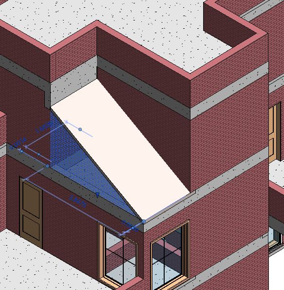
- Go to a 3D view to see the roof clearly.
- Note that the wall on grid E is extending beyond the roof. You can adjust this by attaching the wall to the roof. This will allow the wall to automatically take the shape of the roof when it attached to it.

-
To attach a wall to the roof:
- Select the wall that you wish to attach.
- Go to the tab ‘Modify|Walls’tab -> Modify wall panel -> Attach Top/Base

- Select the roof with which the wall needs to attach.
- Notice that the wall is not attached and has taken the shape of the roof profile.
- When you detach the wall from this roof, the wall will automatically switch back to its original profile.
- When you detach the wall from this roof, the wall will automatically switch back to its original profile.
- Navigate to Section FF.
- Notice the overlapping join between the roof and the beam. If you would like to clean this join, use ‘Join Geometry‘ between these two elements.

- After completing all of the steps above, save as the project as, “TutorialRoof_Output_LearningRevitOnline.rvt”
More about Roofs:
- Create a Roof by Footprint
- Create a Roof by Extrusion
- Explore different shapes of Roofs in a Sample File
- Video Tutorial by Autodesk: Create a Sloped Roof
- Video Tutorial by Autodesk: Create a Dormer Roof
- Learn more about Roof subassemblies:
- Create a Roof from a Mass Face
