About Walls
Unlike CAD tools, Revit elements are information rich and have behavioral patterns as if in a real construction site. For example, a Wall would understand that it must have a height that is connected to a particular level. It understands that it has a thickness, material and a function. All of this information can be given at the time of modeling in Revit or can later be changed once the information is available to you in the project. Windows and Doors, for example, can only be fixed in a wall and cannot be placed anywhere in the project. This is similar to a construction site.
This tutorial is about creating basic walls with single structural layer. If you would like to learn about creating walls with multi-layers (adding layers for finishes, structure, membranes, insulation, etc.), please go to the tutorial Compound Structures.
Tutorial Objective:
In this tutorial, you will learn,
- To create a new wall type
- Place a Wall in a Rectangular shape
- Place a Wall in a Straight Line shape
- Trim/Extend to Corner Tool
- Change the Wall Type after Modeling walls
- Using Reference Planes as Construction Lines
- Offset a Wall
- Using Dimensions to position the wall
- Trim/Extend Single Element Tool
Sample Problem:
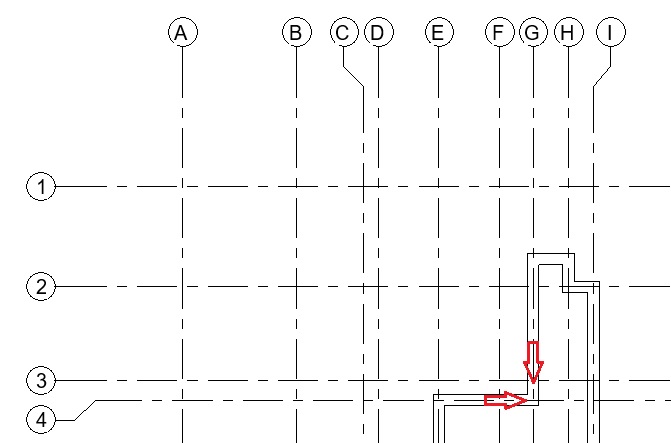
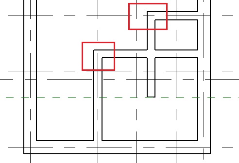
Add basic walls in the sample tutorial project as shown below:
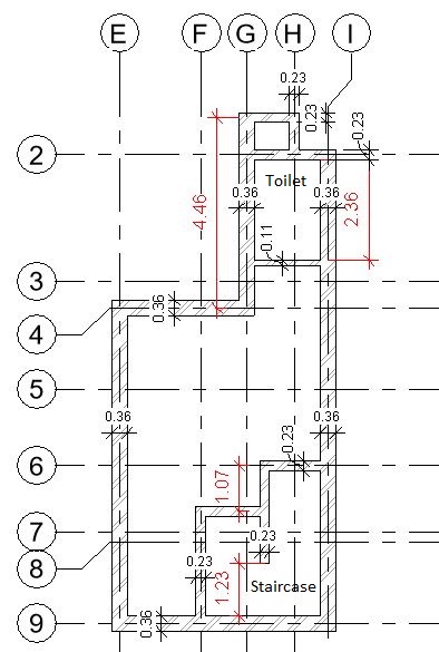
- Wall Base Constraint: -01 Basement Floor Level
- Wall Top Constraint: 00 Ground Level
- Wall Thickness: 360mm, 230mm and 110mm as indicated in Fig 1.
Sample File required for this tutorial: “TutorialWalls_Input_LearningRevitOnline.rvt” (If you do not have this file, please download it from here.)
Solution:
- Open TutorialWalls_Input_LearningRevitOnline.rvt in Revit. This project file already contains Grid lines.
- Navigate to the floor plan of “-01 Basement Floor Level”
- Click Architecture tab -> Build panel -> Wall drop-down -> Wall: Architectural
- Alternatively, use keyboard shortcut ‘WA’.
- As described in Tutorial objective, the project required three types of brick walls with thickness of 360mm, 230mm and 110mm. These types are not available in the project. Thus, let’s create them.
Create a New Wall Type:
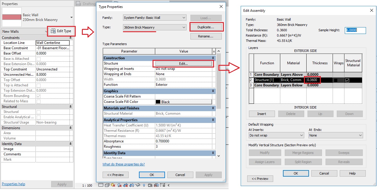
- From the Type Selector, select a “Basic Wall – Generic – 200mm” Type.
- Go to Edit Type-> Type properties dialog box – > Duplicate -> Give a name ” 230mm Brick Masonry”

- Click Ok.
- In the Type Properties dialog box, Go to Structure parameter -> Click “Edit”.
- Edit Assembly dialog box will appear.
- Go to Row 2 which displays ‘Structure’ layer. Under thickness, add value 230mm / 0.23m
- Under Material, click on the button with “…”sign and it will open the material browser.
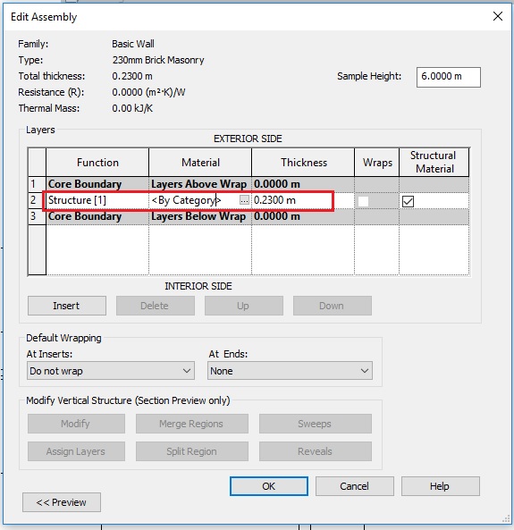
- Select the material “Brick” from the material browser.

- Click OK to Material Browser.
- Click OK to Edit Assembly dialog box.
- Click OK to Type Properties dialog box.
- Now, a new wall type “230mm Brick Masonry” has been listed under Type selector list.
- To create the wall types – “360mm Brick Masonry” and “110mm Brick Masonry”, begin by selecting a “230mm Brick Masonry” Type from the Type Selector. Repeat the process as shown in Step 5 and assign the specified thickness in the Edit Assembly dialog box.
- Now, you have three wall types in the project as required. Let’s begin to model them.
Place a Wall in a Rectangular shape:
- Make sure “-01 Basement Floor Level” view is active currently and you see the Grid lines.
- Let’s begin by drawing 360mm thick outer walls as shown in Fig 1.
- Click Architecture tab -> Build panel -> Wall drop-down -> Wall: Architectural
- Alternatively, use keyboard shortcut ‘WA’.
- From the Type Selector, select ‘360mm Brick Masonry’ wall type.
- From the Draw panel, select Rectangle as shape.
- As the Basement level view is active currently, by default, the base of the wall is taken as the basement level. From the options bar, set the height of the wall by selecting the top constraint as the “00 Ground Level”.
- TIP: If the base level/top level are different or has an offset in height, you can set these values from the Instance parameters in the Properties palette.
- Set the Location Line of the wall as “Wall Center line” as in this case, we want the wall center to align with our Grid lines.
- Now, click on the Grid intersection E-4 to set the starting point of the rectangle.
- Next, click on the Grid intersection I-9 to set the end point of the rectangle.
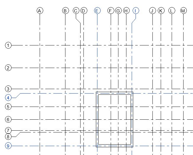
- A rectangular wall is created. Click Esc twice to end the Wall tool.
Place a Wall in a Straight Line shape:
- Now, from Architecture tab -> Build panel -> Wall drop-down -> Wall: Architectural -> select Straight Line tool.
- From the options bar, make sure Chain option is checked.
- Note that the height of the wall is now automatically taken as Ground Level as Revit continues to use the previous setting.
- Click the starting point of the wall as the Grid intersection G-4
- Move your mouse upwards towards the Grid G and enter on your keyboard the exact length of the wall which is 4.46m
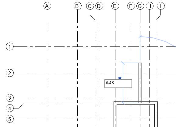
- As the chain option was checked, Revit will allow you to draw more walls without ending the Wall tool.
- Click the next point of the wall horizontally till it meets Grid H.
- Move your cursor downwards vertically and click the next point for the wall at Grid intersection H-2.
- Click the next point for the wall at the Grid intersection I-2.
- Click Esc twice to end the wall tool.
- Now, we want to connect the vertical gap between Grid I-2 and I-4. One approach would be to draw another vertical wall. But more efficient approach would be to use Trim/Extend tool to close this gap. Use this tool when you want to create L-shaped corners.
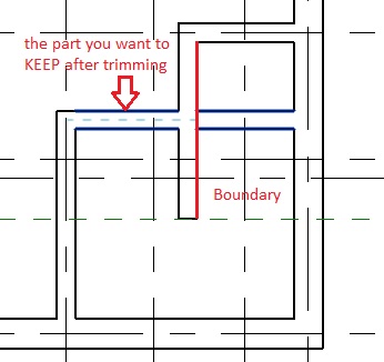
Trim/Extend to Corner Tool:
- Go to Modify Tab -> Modify Panel -> select Trim/Extend to Corner
- Alternatively, use keyboard shortcut ‘TR’.
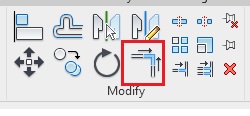
- Alternatively, use keyboard shortcut ‘TR’.
- First click on the horizontal wall and then on the vertical wall as shown below to form a L-shaped corner at the Grid intersection I-2.
- Note that vertical wall has been extended and the horizontal wall has been trimmed to create a clean L-shaped corner joint.
- Click Esc to end the Trim/Extend to Corner tool.
- Go to Modify Tab -> Modify Panel -> select Trim/Extend to Corner
- Repeat step 11, to create a L-shaped corner at Grid intersection G-4 as shown below.
- Now, as per Fig 1, the three walls between Grid G-I are of 230mm thickness. However, in our project, it is currently of 360mm thickness. To change a wall type after it is modeled, do the following.
Change the Wall Type after Modeling walls:
- Select the walls as shown below.
- TIP: Select one of the walls. Press Ctrl while you select other walls. This will add other walls to the selection group. Press Shift and click on a wall, if you wish to deselect it from the selection group.
- Go to the Type selector and click on the Wall type “230mm Brick Masonry”.
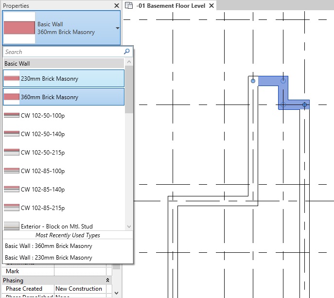
- Click Esc to deselect the walls. Note that the selected walls have been converted from “360mm Brick Masonry” wall type to “230mm Brick Masonry” wall type.
- Select the walls as shown below.
- Now, let’s model some walls surrounding the staircase area as shown in Fig 1.
- Go to Architecture tab -> Build panel -> Wall drop-down -> Wall: Architectural -> select Straight Line tool.
- From the Type Selector, select the wall type “230mm Brick Masonry”.
- Using the process shown in step 9, draw walls between Grid intersection F-9 to F-6 and from F-6 to I-6. See image below.

- Click Esc to end wall tool.
- Let’s create the middle vertical line of the staircase area as shown in Fig 1. To draw this wall as per its exact length, we will need some construction/reference lines. This can best be done in Revit using Reference Planes as described below.
Using Reference Planes as Construction Lines:
- Go to Architecture tab -> Work Plane panel -> Ref Plane
- Alternatively, use keyboard shortcut ‘RP’.
- Draw a horizontal plane as shown below. There is no need to be accurate about exact position/dimension of the plane. Draw it like you would draw a line.

- Click Esc twice to end the Ref Plane tool.
- Select the reference plane you just created.
- A temporary dimension will appear between the reference plane and the inner face of the parallel horizontal wall below.
- TIP: Click on the blue dot on the temporary dimension to switch the witness line reference from the inner face of the wall to its center or outer face.
- Click on the dimension value and change it to 1.23m between the reference plane and the inner face of the wall. Press Enter.

- Click Esc to deselect the reference plane.
- Go to Architecture tab -> Work Plane panel -> Ref Plane
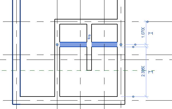
- Now place a vertical wall in a straight line (the process as shown in step 9), starting from the mid point of the wall on Grid 6 and ending at the reference plane as shown below.

- You can now select and delete (use Delete key on your keyboard) the reference plane as we do not need it further in our project.
- As per Fig 1, we need a horizontal wall that is 1.07m away and parallel to the wall on Grid 6. One approach to do this would be to offset the wall at required distance as shown in the steps below.
Offset a Wall:
- Go to Modify Tab -> Modify Panel -> select Offset
- Alternatively, use keyboard shortcut ‘OF’.
- On the options bar, select Numerical. Give the Offset value as 1.07m.
- On the options bar, keep the Copy option checked. This will ensure that a new instance of the wall is created at the offset distance from the wall you pick.
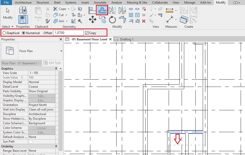
- Hover your cursor on the wall at Grid 6 pointing in a direction you want offset to be created. Revit will show you a blue dotted line indicating where the wall will be placed. If this is correct, click where your cursor is. If not, move your cursor in the direction of your offset and click when the blue line displayed is at a correct location.
- A copy of the wall picked (having the same type 230mm Brick Masonry and same length) is created at an offset distance of 1.07 m.
- Click Esc to end the Offset tool.
- Go to Modify Tab -> Modify Panel -> select Offset
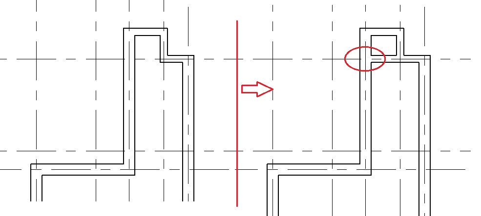
- Using Trim/Extend to Corner Tool (the process as shown in step 11), make L-shape corners as shown in the image below:
- To create L-corners, the Trim/Extend to Corner tool is the most efficient modify tools available. However, we cannot use it to create T-junctions as we would like to to do for the vertical wall in the middle. Thus, to do this, use Trim/Extend Single Element tool as shown in the steps below:
Trim/Extend Single Element:
- Go to Modify Tab -> Modify Panel -> select Trim/Extend Single Element
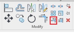
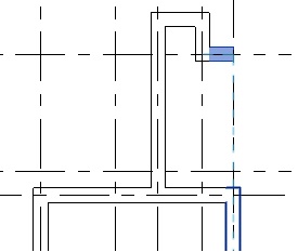
- Click the face of the the middle vertical wall as the boundary for trimming.
- Click on any point on the part of the horizontal wall that you would like to KEEP (not trim) – in this case, left of the vertical wall.
- You will note that the horizontal wall has been trimmed and a T-junction has been created.
- Click Esc to end the Trim/Extend Single Element tool.
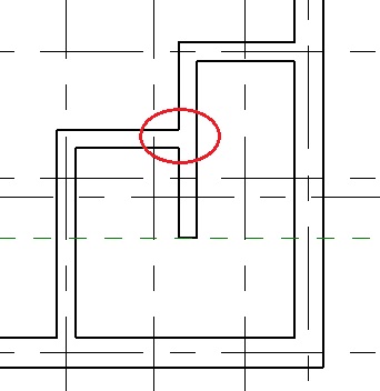
- Go to Modify Tab -> Modify Panel -> select Trim/Extend Single Element
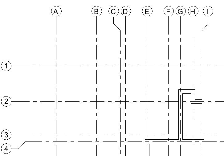
- Using the Trim/Extend Single Element tool as shown in the above step, create a T-Junction at the Grid intersection G-2 as shown in the image below:
- As shown in Fig 1, a partition wall of 110mm thickness shall be created to enclose the toilet area.
- One approach would be to offset a horizontal wall on Grid 2 at the specific distance (as shown in step 25) and then changing the wall type (as shown in step 14) of the offset wall from 230mm to 110mm as required.
- Another approach would be to draw the wall and then use dimensions to place it at the exact location as shown in the steps below.
Use Dimensions to position the wall:
- Go to Architecture tab -> Build panel -> Wall drop-down -> Wall: Architectural -> select Straight Line tool.
- Select wall type “110mm Brick Masonry” from the Type Selector.
- Draw a horizontal wall as shown below. Do not worry about exact position of the wall at the moment. Draw it at an approximate position.
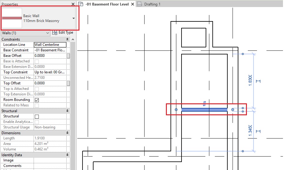
- We need to position the wall at 2.36m from inner face of the upper wall (at Grid 2) to the inner face of the 110mm wall we have created.
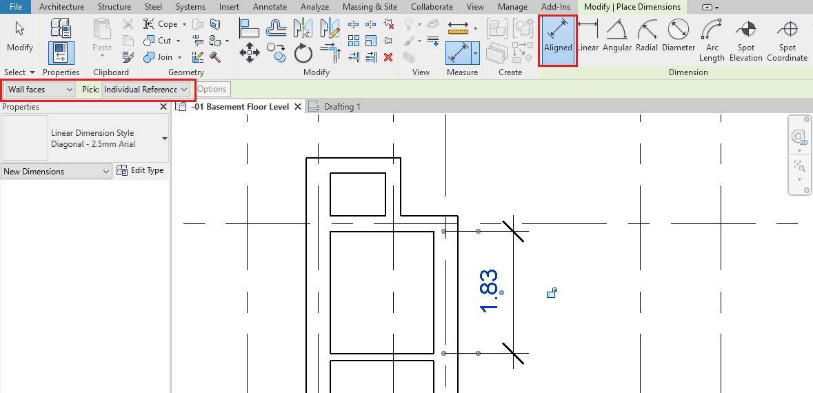
- Go to Annotate tab -> Dimension panel -> select Aligned Dimension
- Alternatively, use keyboard shortcut “DI”
- On the Options bar, select Wall faces and Pick option as Individual References.
- In the drawing area, click on the inner face of the 110mm partition wall. Next, click on the inner face of the wall at Grid 2. Lastly, click where you want to place the dimension in the drawing ( Try to click somewhere in the middle of the dimension instead on its end as you might do in a CAD tool.)
- Click Esc twice to finish Dimension tool.
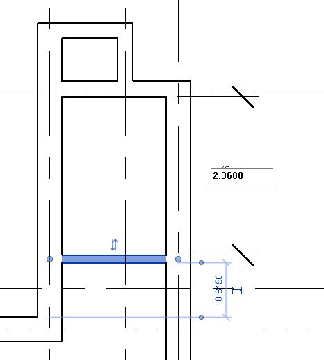
- Click on the 110mm partition wall.
- The dimension text will be highlighted as blue indicating that it is now editable.
- Note: You cannot change the value of the dimension without selecting the element it refers to. Revit must know which element it should move if the dimension value changes. And thus, it activates the dimension only when the element is selected.
- Click on the text of the dimension and change its value to 2.36m
- The partition wall will move as per the dimension specified.
- Click Esc to deselect the wall.
- You may select the dimension and delete it if you do not need it further.
- All the walls as per Fig 1 has been created.
- Navigate to a 3D view from your project browser to view your model in 3D.

- After completing all of the above steps, Save As your project as “TutorialWalls_Output_LearningRevitOnline.rvt”.
TIPS
- Learn more about Wall Location Lines here.
- TIP: TAB to select multiple walls: To place/select walls simultaneously on an entire chain of lines, move the cursor over a line segment, press Tab to highlight them all, and then click.
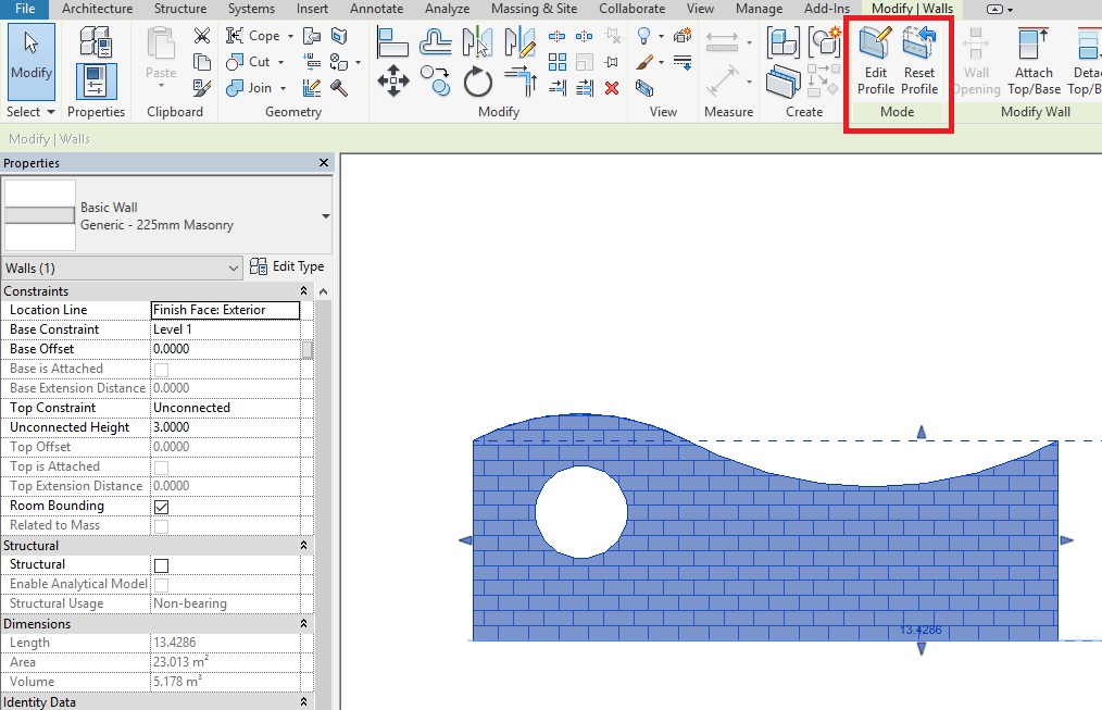
- TIP: Edit Profile of the Wall: When you place a straight wall, it has a rectangular profile when viewed in elevations. If your design requires a different shape/profile, or for openings in the wall, you can edit the wall’s elevation profile in a section view or an elevation view. Learn more about this method here: How to edit a wall profile?
Q&A
Have any Questions? or Suggestions? or Feedback? Please feel free to Contact Us, we will get back to you as soon as we can.
