About Components
Components are those building elements that are usually delivered and installed on site – such as furniture, plumbing fixtures, lighting, etc. Components are loadable families, which need to be loaded in the project from your content library.
There are free standing components such as furniture or equipment placed on a floor/level. There are also host-based components which are dependent on a building element that acts as a host such as a wall lamp that has wall as its host. When a wall is moved/deleted, the dependent component is also moved/deleted. Usually, the wall, floor, level/work-plane, roof, ceiling or a face of an object work as a host for components.
Tutorial Objective:
In this tutorial, you will learn,
- To place a component in the model
- To place a host-based component
- Use Create Similar tool
- To move a host-based component to a different host
Sample Problem:
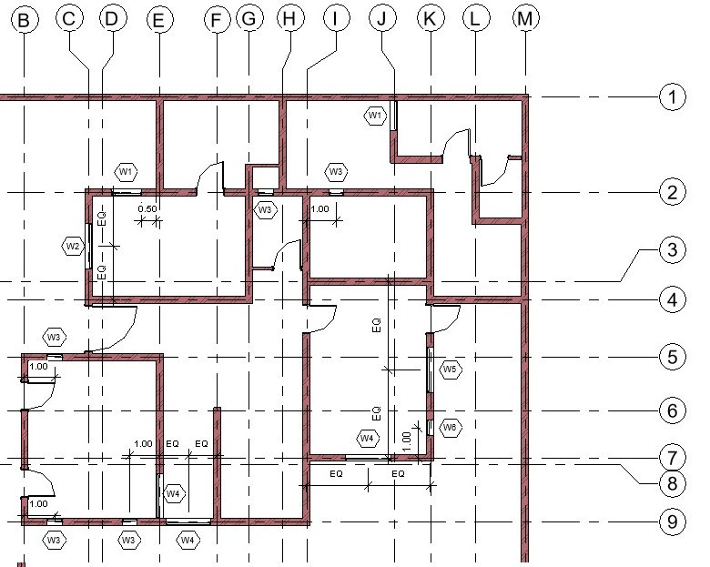
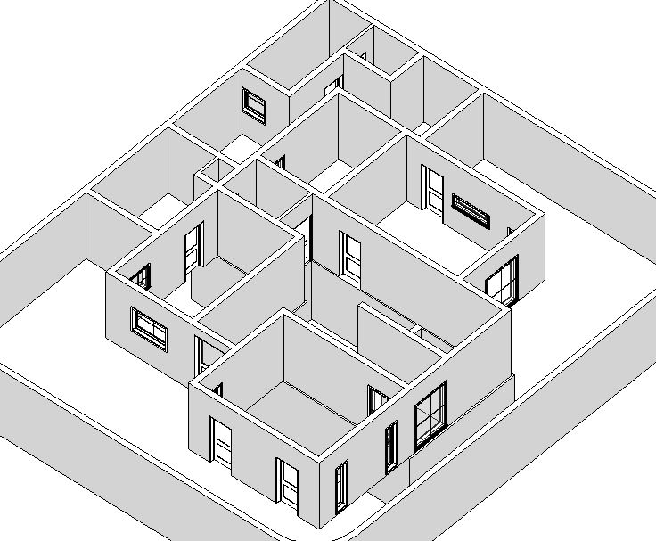
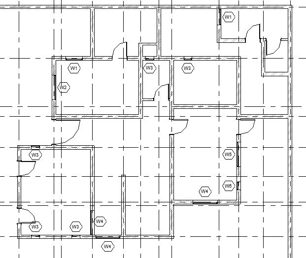
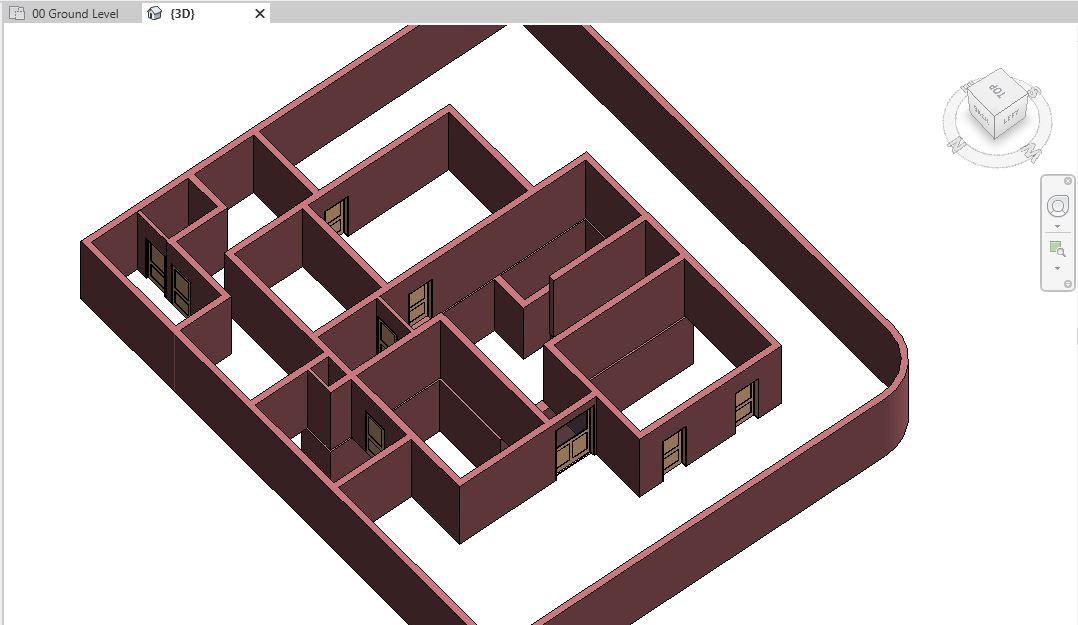
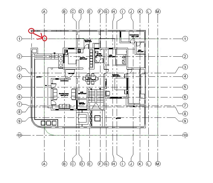
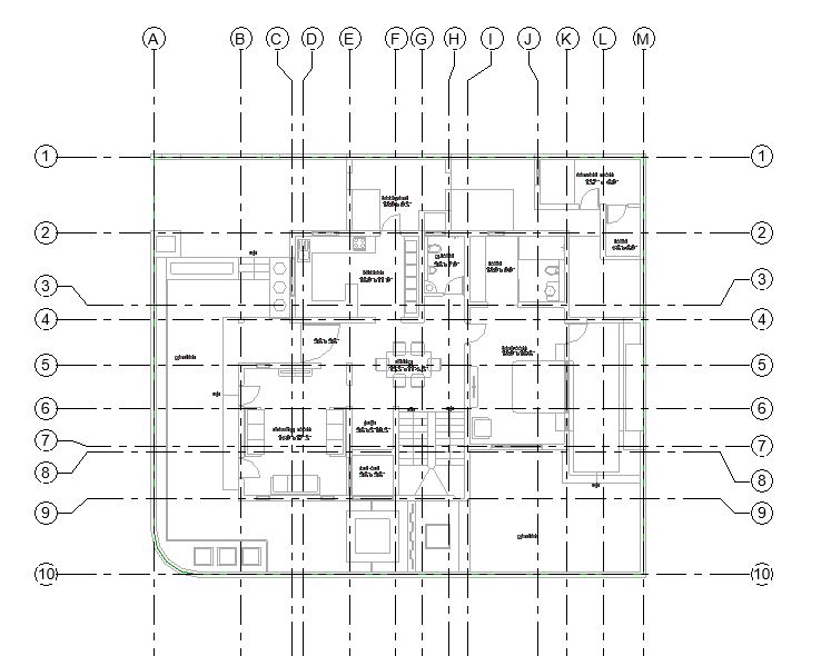
Add 3 instances of Furniture_Sofa.rfa and 2 instances of Plumbing_WC.rfa components to the Ground Floor layout as shown in Fig 1.

Sample Files required for this tutorial:
If you do not have the following files, please download them from here.
- “TutorialComponent_Input_LearningRevitOnline.rvt”
- Component Family file: “Furniture_Sofa.rfa” and “Plumbing_WC.rfa”
Solution:
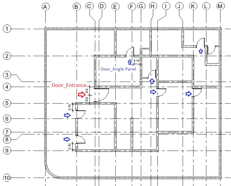
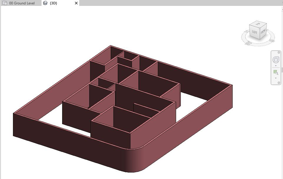
- Open ‘TutorialComponent_Input_LearningRevitOnline.rvt’ in Revit. This project file already contains doors and windows modeled in the Ground Floor levels.
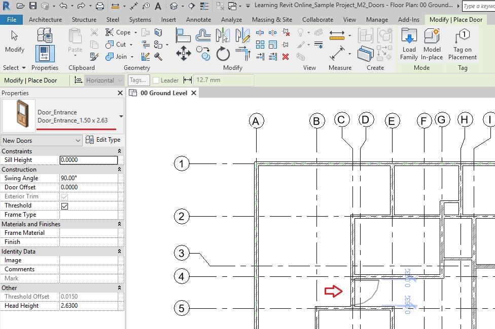
- Navigate to the floor plan of “00 Ground Level”.
- Load the component families “Furniture_Sofa.rfa” and “Plumbing_WC.rfa” into the project.
- Click Insert tab -> Load from Library panel -> Load Family -> Navigate to the folder where above families are located on your computer -> Select them -> Open.
-
To place a component:
- Go to Architecture tab -> Build panel -> Place a Component
- Alternatively, use “CM”as keyboard shortcut.
- Select the type for the Furniture_Sofa family from the Type selector.
- In the drawing area, place the sofa as shown below. Press Spacebar to change the orientation of the sofa. Do not worry about the exact position at the moment which can be adjusted after the sofa has been placed.

- Click Esc twice to end the Components tool.
- Go to Architecture tab -> Build panel -> Place a Component
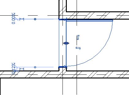
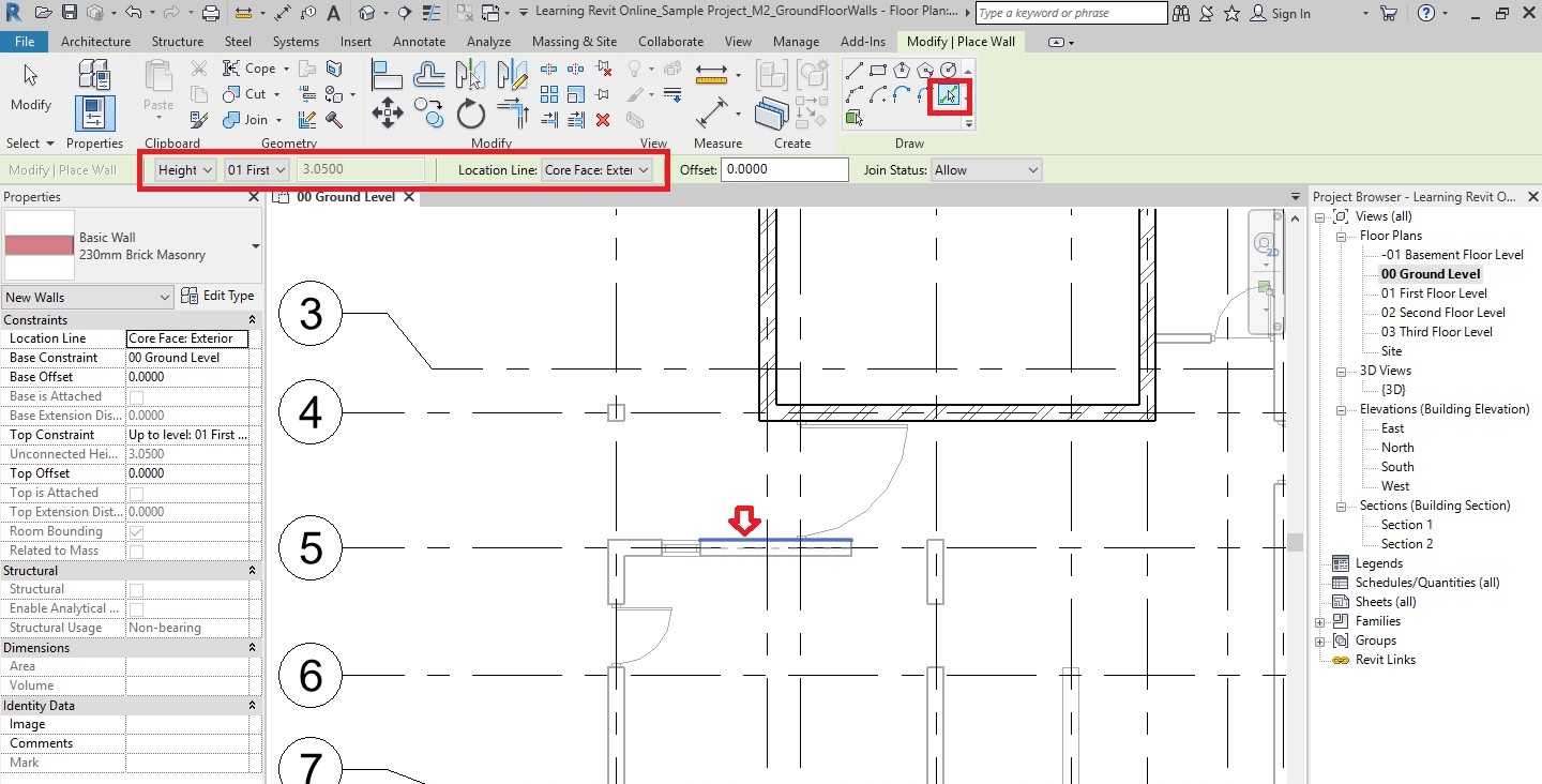
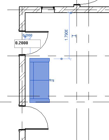
- Click on the Sofa that you have placed. Temporary dimensions will appear. Use these dimensions to locate the sofa 0.2m away from the edge of the wall behind it.
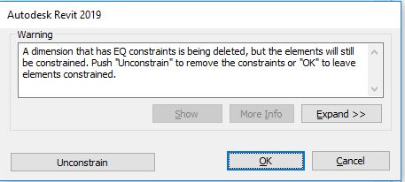
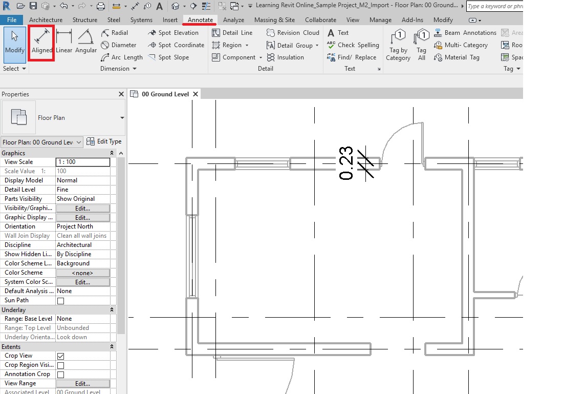
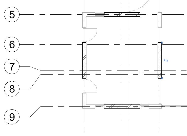
- Now, position the sofa exactly in the middle of the Grid 5 – 9 by using equality constraint as shown below.
- To learn how to use equality constraint, click here.

- To learn how to use equality constraint, click here.
- Repeat step 4-6 to place two more instances of sofa as shown below.

- Let’s now, place a WC in the toilet, which is a host-based (dependent on the wall) component.
-
To place a host-based component:
- Ensure that you have already loaded the family Plumbing_WC in your project.
- Go to Architecture tab -> Build panel -> Place a Component
- Alternatively, use “CM”as keyboard shortcut.
- Select the type for the Plumbing_WC family from the Type selector.
- In the drawing area, notice that you cannot place this component anywhere. If you take your cursor to a wall, only then you are able to place this component as it requires the wall as its host.
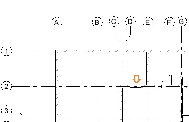
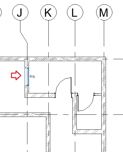
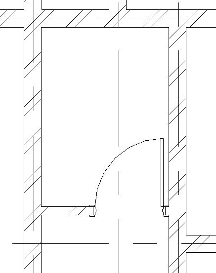
- Click on the wall on Grid-G as shown below to place the WC in its position.

- Click Esc to end the component tool.
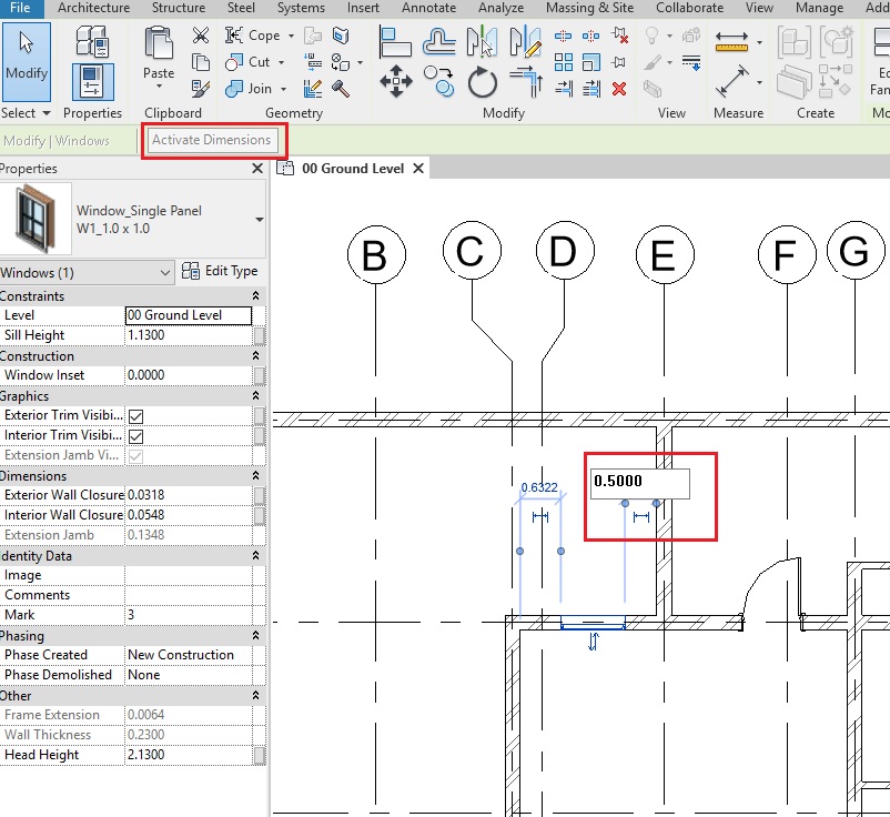
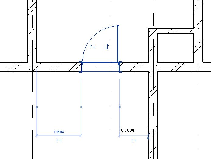
- Select the WC after placing it. Using the temporary dimensions, adjust the position of the WC to be 0.5m away from the inner face of the wall on Grid 2 as shown below.

- Click Esc to deselect the component.
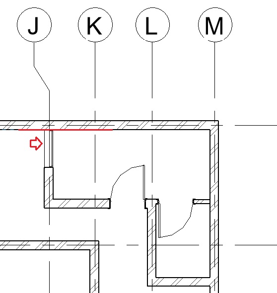
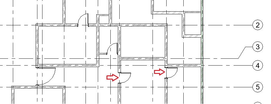
- Now, let’s create one more instance of the same type of WC in another toilet area of the project as shown below. However, instead of using a Component tool, you can use “Create Similar” tool to be more efficient.

-
To use create similar tool:
- As you want to make more instances of the same type of family, select the instance already in the model.

- Go to Modify tab -> Create panel -> Create Similar ( OR “CS”as keyboard shortcut). If you have selected a component, Component tool will be active and the same type from the type selector will be automatically selected.
- Now, you can continue to place more instances of the same type.
- Create similar tool works across all Revit elements (ex. walls, grids, doors, etc), it immediately activates the tool required to create another instance of the same type selected of that particular family. Adds wonders to your productivity !!
- As you want to make more instances of the same type of family, select the instance already in the model.
- Adjust the position using temporary dimensions as required after placing the component.
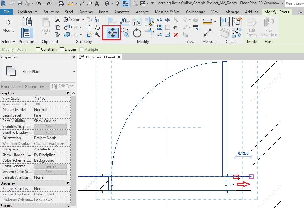
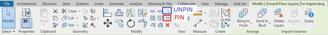
- After placing a host-based component, if you would like to move it another host, Move tool will not be very effective. Instead, use “Pick New Host”tool.
-
To move a host-based component to a different host:
- Select the component you want to move.
- Go to Modify tab -> Host panel -> Pick New Host tool.
- Select a different host element for the component and place it at the required position.


- Note: If the component is wall-based, you can only select a new host for that component to be a wall. It cannot be placed to a different category of host for which it has not been created.
- Click Esc to end the Pick New Host tool.
- After completing all the steps above, Save As your project as “TutorialComponent_Output_LearningRevitOnline.rvt”.
More References:
Some of the popular online libraries to download Revit components are: