Make sure that you have completed the Tutorial Import a CAD drawing and Modelling Basic Walls, before moving on with this tutorial.
Tutorial Objective:
In Modelling Basic Walls chapter, we learnt about modelling basic walls, Trim/Extend Tools and using dimensions for modeling purposes. Please make sure that you are familiar with these tools as well as how to Import/Link a CAD drawing, before starting with this tutorial.
In this tutorial, you will learn,
- To hide layers of the CAD file
- To query a CAD file
- To place a dimension
- To sketch walls by snapping on the CAD lines
- To model walls using Pick Line tool
- Trim/Extend Multiple Element Tool
- To hide the imported CAD file
Sample Problem:
- Add walls for the Ground Floor of the sample project as shown below. Use the linked/imported CAD drawing “Ground Floor Layout_For Import.dwg” as reference. (as imported in previous chapter Import a CAD drawing).

Sample Files required for this tutorial:
If you do not have the following files, please download them from here.
- “TutorialWallsCAD_Input_LearningRevitOnline.rvt”
- “Ground Floor Layout_For Import.dwg”
Solution:
- Open ‘TutorialWallsCAD_Input_LearningRevitOnline.rvt’ in Revit. This project file already contains “Ground Floor Layout_For Import.dwg” imported into the floor plan view of “00 Ground Level”. It also contains the basic wall types required for the project.
- NOTE: To learn the process of creating wall types, refer Modelling Basic Walls
- Navigate to the floor plan of “00 Ground Level”. Notice the Imported CAD drawing in the view.
- Now, before modelling walls, let’s hide the layers of the CAD drawing which are not necessary for us at the moment.
-
To hide layers of the CAD file:
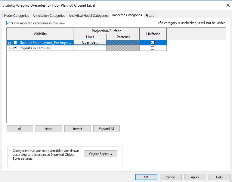
- Go to View tab -> Graphics panel -> Visibility Graphics -> Visibility Graphics Override dialog box will appear.
- Alternatively, use “VG” as a keyboard shortcut.
- Go to Imported Categories tab.
- Expand the row with the name of the CAD file: Ground Floor Layout_For Import.dwg
- The list of all layers available are present.
- Turn off the checkbox for layers you do not need. For example, furniture layer with the name “FUR”.

- Say OK.
- You will notice that the elements present in the FUR layer (Furniture) is turned off in the drawing area.
- Go to View tab -> Graphics panel -> Visibility Graphics -> Visibility Graphics Override dialog box will appear.
- If you do not know which elements are in which layer, you can also use Query tool to identify and hide the layers.
-
To query a CAD file:
- Select the CAD file in the drawing area.
- Under Modify tab-> Import Instance panel -> select Query
- Select the part of the CAD file for which you would like information. For example, select the text in the Grid bubble of the CAD file as shown below.

- Import Instance Query dialog box will appear showing the information of the selected element.
- Choose “Hide in View” to hide the shown layer from the drawing area.
- Continue to make further queries, if you like.
- After completing, Click Esc to end the Query tool.
- Using Steps 4 and 6, turn off all layers except layer “wall”(for walls) and “dw”(for doors and windows).

- Now, let’s create the walls of the kitchen room between Grid C-2 and G-4.
- First, we will have to know the wall thickness/wall type required.
- Use dimension tool to know the wall thickness.
-
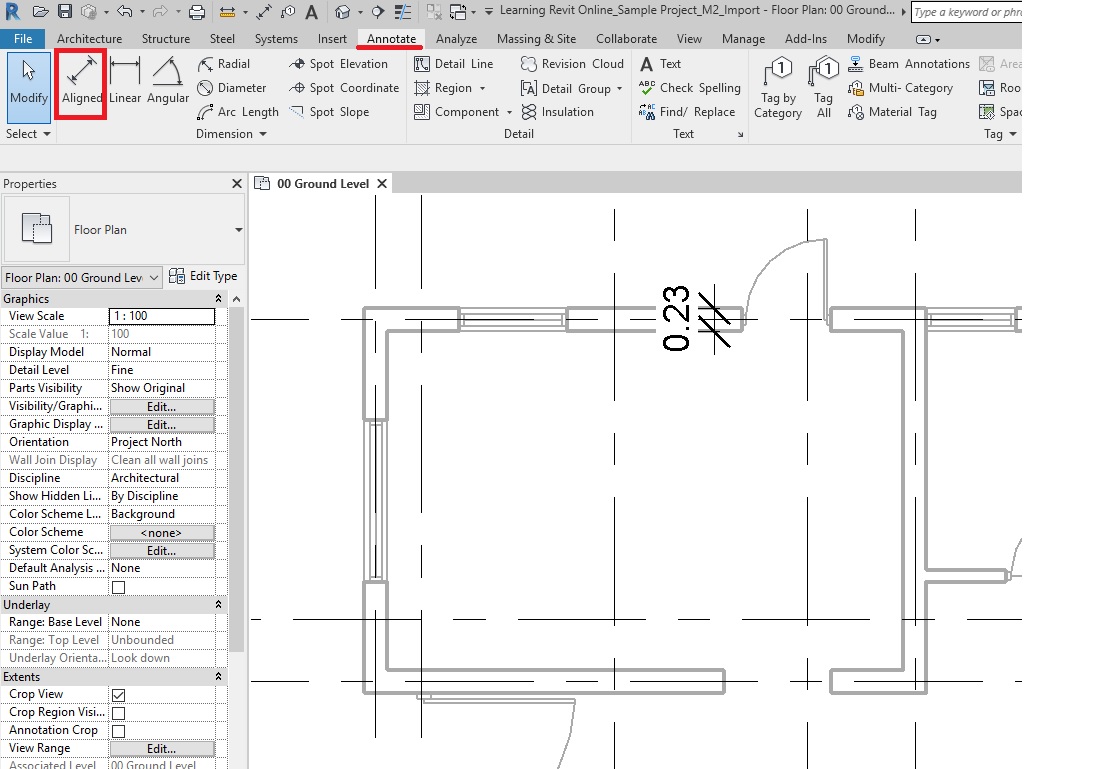
To place a dimension:
- Go to Annotate tab -> Dimension panel -> Aligned
- Alternatively, use “DI”as a keyboard shortcut.
- Click the line (of the CAD file) at the face of the wall.
- Click on the other face of the wall for which dimension is needed.
- Click in an empty space to place the dimension.
- In this case as shown below, the wall thickness is 230mm/0.23m
- Go to Annotate tab -> Dimension panel -> Aligned
- Now, there are two ways to model walls. One is to sketch the wall in a rectangular/striaght line shape snapping on the CAD lines. The other is to use ‘Pick line’ tool. Let’s learn both.
- At this point, ignore the openings for Doors and Windows. When Doors and windows are modeled, openings will be made automatically by Revit in the walls.
-
To sketch walls by snapping on the CAD lines:
- Click Architecture tab -> Build panel -> Wall drop-down -> Wall: Architectural
- Alternatively, use keyboard shortcut ‘WA’.
- From the Type Selector, select ‘230mm Brick Masonry’ wall type.
- From the Draw panel, select Rectangle as shape.
- On the options bar, select Location Line as the Core Face Exterior as we want to match the exterior brick face of the wall to the outer rectangle in CAD. (Learn more about Location Line here).
- On the options bar, Set the Height constraint to “01 First Floor Level”.
- Enter the start and end point of the rectangle by snapping on the CAD lines as shown below.

- The rectangular wall has been created.
- Click Architecture tab -> Build panel -> Wall drop-down -> Wall: Architectural
- Let’s model walls between Grid B-5 to E-9 using ‘Pick Lines’ tool.
-
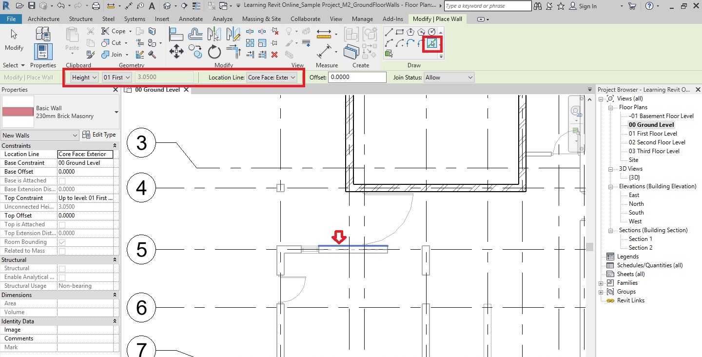
To model walls using Pick Lines tool:
- Click Architecture tab -> Build panel -> Wall drop-down -> Wall: Architectural
- Alternatively, use keyboard shortcut ‘WA’.
- From the Type Selector, select ‘230mm Brick Masonry’ wall type.
- On the options bar, select Location Line as the Core Face Exterior as we want to match the exterior brick face of the wall to the outer rectangle in CAD. (Learn more about Location Line here).
- On the options bar, Set the Height constraint to “01 First Floor Level”.
- From the Draw panel, select ‘Pick Lines’ tool.
- In the drawing area, select the edge/line of the CAD file as shown below where you would like to place a wall. A blue dotted reference line will be shown while you try to select the line – to show in which direction the wall will be placed. Keep your cursor towards the direction where you want to place the wall and then when the dotted reference is showing correctly, click to place the wall.
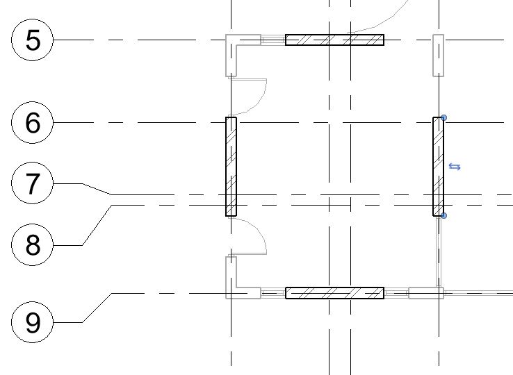
- The wall has been placed of the length equal to the line selected.
- Similarly, select lines/edges in all four directions of the room – as shown below.
- TIP: . In CAD, lines that you pick may not represent the actual length of the wall. Instead of picking multiple lines and create more instances of the walls along the length of the wall, use Trim/Extend tools to reduce the number of Instances.
- TIP: . In CAD, lines that you pick may not represent the actual length of the wall. Instead of picking multiple lines and create more instances of the walls along the length of the wall, use Trim/Extend tools to reduce the number of Instances.
- Using Trim/Extend to Corner tool connect all four walls in a rectangular shape.
- Go to Modify Tab -> Modify Panel -> select Trim/Extend to Corner
- Alternatively, use keyboard shortcut ‘TR’.
- Click on the two walls between which a L Corner is needed to be created.
- Go to Modify Tab -> Modify Panel -> select Trim/Extend to Corner
- A rectangular wall between Grid B-5 to E-9 has been created.

- Click Architecture tab -> Build panel -> Wall drop-down -> Wall: Architectural
- Now, let’s create more walls between Grid G-2 and K-4.
- Using Pick Lines tool (as shown in step 16), create walls of 230mm wall type on vertical Grid I and K as shown below.

- Using Trim/Extend to Corner tool connect the wall on Grid 2 with Grid K.
- Note on Best Practice: Now, instead of creating an additional horizontal instance on Grid 2, it is better to use Trim/Extend to Corner tool to extend the length of the wall to connect with the vertical walls added in the previous step 18.
- Using Pick Lines tool (as shown in step 16), create walls of 230mm wall type on horizontal Grid 3 and 110mm wall type on the partition wall located slightly above Grid 3 as shown below.

- Using Trim/Extend Multiple Element, extend these walls towards the vertical wall on Grid I.
-
To Trim/Extend Multiple Element:
- Go to Modify Tab -> Modify Panel -> select Trim/Extend Multiple Element
- Click on the vertical wall on Grid I to define the border for extension.
- Click on the horizontal walls around Grid 3 that needs to be extended.
- A Tee-Junction has been created between these walls.
- Click Esc to end the tool.

- To draw other walls on the Ground Floor layout as shown below, use either the sketch walls (as shown in step 14) or Pick Lines tool (as shown in step 16). Reduce the number of instances by using Trim/Extend tools.

- TIP: Switch to “Shaded” visual style to clearly see where the walls have been already modeled.
- Go to View Control Bar -> Visual Style -> Graphic Display Options -> Shaded

- Go to View Control Bar -> Visual Style -> Graphic Display Options -> Shaded
- TIP: Switch to “Shaded” visual style to clearly see where the walls have been already modeled.
- After completing modeling all walls, you may choose to hide the imported CAD file to see the Revit model clearly.
-
To hide the imported CAD file,
- Go to Visibility Graphics (“VG”as a keyboard shortcut).
- Go to Imported Categories tab -> Select the Imported CAD file and turn off the checkbox beside the name of the CAD file.
- Say OK.
- The CAD file is now hidden from the view. If you want, you can repeat the step 25 and turn on the checkbox in the visibility graphics to unhide the imported CAD file.
- After all the walls are created and if you do not need the imported CAD file, you may select and delete it from the project.
- TIP: If you have linked your CAD file, then you may unload the link by going to Insert -> Manage Links -> CAD Formats -> Unload. When you need the file again, you can Reload it in the project. If you are sure that you do not need the linked file again, then you can also remove it instead of unloading it.
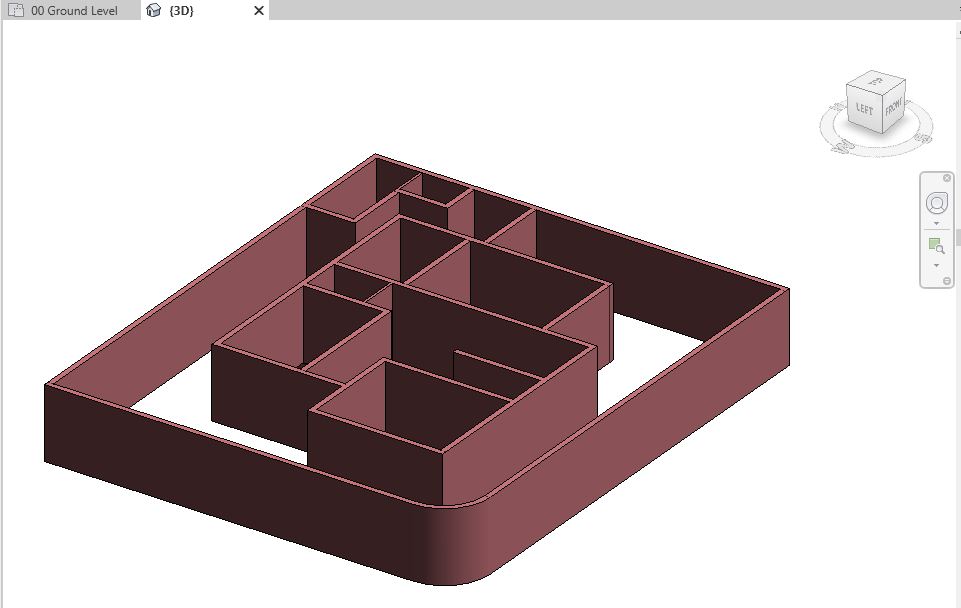
- Navigate to a 3D view to see all the walls in 3D.
- After completing all the steps above, Save As your project as “TutorialWallsCAD_Output_LearningRevitOnline.rvt”.
More References:
- Import a CAD drawing
- Modelling Basic Walls
- Video Tutorial by Autodesk: Control Visibility and Graphic Display
- Learn more about Graphic Display Options
