Elevation views are used to view the project either from its exterior or interior face. Using the elevation tag that snaps to the direction of the wall, you can set your elevation view.
Video Tutorials
Learn about how to create elevation views with this Video Tutorial – by Autodesk
Sometimes, you want to refer to an existing elevation view or drafting view to help the reader understand the view being displayed. In such cases, you can create a Reference elevation that does not create a new view but refers to the existing view.
Structural floor plans offer the possibility to change the direction of view either to looking down or looking up. For example, if your view needs to look at the foundations, you can set the view direction to down while for structural beams, you can set the direction to up.
In this tutorial, we will talk about creating Building Pads and adding Site components (such as trees, bench, street lights, parking spaces, etc).
Building Pads
To flatten a piece of land on your site in order to position your building, use building pads. Building pads can only e created on a Toposurface. Revit will be able to automatically fill/cut the Toposurface in order to position the building pad on the specified elevation.
Learn about creating a building pad with this Video Tutorial – by Autodesk
Site Components
Site components are components whose host is a Toposurface. You can add Site Components such as trees and other plantings, landscape elements such as bench, street light, etc, Logistics elements such as parking spaces, vehicles, etc and other site development components.
Learn about creating a toposurface by defining points in this video tutorial – by Autodesk
Create a Toposurface with Points File:
Sometimes, you receive a points data file from the Site Surveyor using which you may like to create a topographical surface in Revit. Before importing the points file, please ensure that your imported file matches the following requirements:
The points file must be in a comma-delimited file format (a CSV or TXT file).
The file must contain x, y, and z coordinate numbers as the first numeric values in the file.
Any additional numeric information for a point must occur after the x, y, and z coordinate values.
Most surveyors or site engineers use CAD to collect the data points for the topography survey. If you have received a DWG file that you would like to import in Revit and create your toposurface, you can use the tutorial below.
Learn about how to create a toposurface from a DWG file with this Video Tutorial – by Autodesk. Although, this tutorial is created using Revit 2011 version, the method shown here is also applicable to other Revit versions 2011 and above.
Learn about how to grab real world geo-location sites from SketchUp, convert them to DWG and bring them to Revit using this video tutorial – by HowNowVideos
Create subregions in Toposurface
If you would like to mark up an area on your toposurface that contains a different material such as green spot of grass, parking lot, road, etc, you can create a subregion. A subregion adapts to the contours of the toposurface and is dependent on it. Thus, if you delete the toposurface, the subregion also gets deleted.
Learn about how to create subregion on the toposurface using this Video Tutorial – by Autodesk
Split and Merge Toposurfaces
If you would like to split your toposurface in two independent surface and then edit them separately, you can use Split Surface tool. Use Merge tool to join two surfaces into one.
Learn about the difference between Split Surface and Subregion with this Video Tutorial – by emanuel Kantbronce
Learn about how to merge two toposurface with this Video Tutorial – by John Bordeau
Create a Graded Region
Graded regions are created when you want to compare your original toposurface with the proposed site design. Revit will mark the existing surface as demolished phase and a copy of it will be created as a new surface in the current phase for you to work on the proposed site design. You can later compare these two surfaces to calculate total cut/fill volumes.
Learn how to create a graded region with this video tutorial – by Autodesk
Report Cut/Fill Volumes
Revit can report cut and fill volumes on a site by comparing two surfaces from different phases. Creating a graded region is a helpful tool to create a copy of the toposurface in the current phase and work on the proposed site development which can then be compared with the original toposurface.
Learn about how to calculate cut/fill volumes with this video tutorial – by Autodesk
Property Line
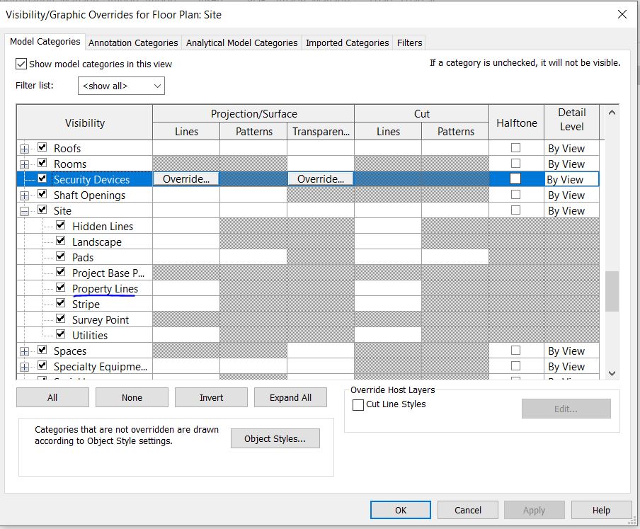
Use property lines to mark the area of your property on Site. Property lines automatically calculate the area of the property and can be tagged, scheduled as well as exported. By default, the property lines are visible only on Site plan. To enable its visibility on other view, adjust Visibility Graphics.
Learn how to create a property line by adding distances and bearings from a site survey and add setbacks to the site plan with this video tutorial – by Jonathan Falkinburg
You can import pages from a PDF file or Images (like JPG, TIFF, PNG, BMP, etc) into your Revit views to use them as references or trace over them to building your model.
Video Tutorial
Learn about how to add a page from a multi-page PDF into a Revit view with this video tutorial – by Autodesk
Learn about how to add a raster image in Revit View with this Video Tutorial – by Autodesk