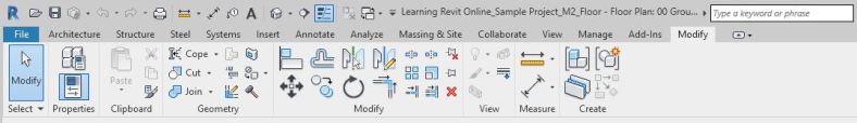
Floors are defined in Revit by boundaries either sketched using drawing tools or by picking walls. Floors are created downwards from the level on which they are sketched. Thus, by default, top of the floor is aligned with the level line.
You create floors by defining their boundaries, either by picking walls or using drawing tools.
Create a structural floor slab with boundary as highlighted in Fig 1, at “00 Ground Level” and “01 First Floor” of the sample project. The floor slab shall be 100mm thick and of Concrete Material.
Fig 1. Floor Slab of the sample project
Sample Files required for this tutorial:
If you do not have the following files, please download them from here.
“TutorialFloors_Input_LearningRevitOnline.rvt”
Solution:
Open the tutorial file ‘TutorialFloors_Input_LearningRevitOnline.rvt’ in Revit. This project file already contains walls on Ground level.
As we want to create a floor under the Ground level, navigate to the floor plan of “00 Ground Level”.
As this would be a structural floor/slab, we will use Structural Floor tool.
To create non-structural floors, use Architectural floors (Architecture tab -> Build panel -> Floor drop-down ->Floor: Architectural)
To add a structural floor slab:
Go to Structure tab -> Structure panel -> Floor drop-down -> Floor: Architectural
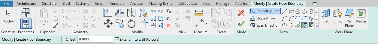
Revit will enter into a Sketch mode. The tab ‘Modify|Create Floor Boundary’ will become active.
Select the type of floor you would like to create from the Type Selector. For this tutorial, select ‘Generic 150mm’.
To manually sketch the boundary, you can use the drawing tools available in the Draw panel. But, as the walls are already available in the layout which define the floor boundary, we will use “Pick Walls” tool.
Pick walls that define the boundary of the floor in the drawing area as shown below.
TIP: As you pick walls, the flip arrows will appear on the line. Use this flip arrow to flip the line between the inner and outer boundary of the wall.
In a sketch mode, no lines can overlap or intersect each other. Use modify tools such as Trim/Extend to make a closed loop as shown below.
After drawing the boundary, click Finish Edit Mode to end the Sketch mode.
Revit may give you a notification whether you would like to attach the highlighted walls to the floor. For now, select No.
Note: If the floor moves in elevation, attached walls will adjust their height accordingly. Select ‘Yes’ if you want this effect to happen. Select ‘No’ if you do not want this to happen.
Go to a Section view to see the Floor. Notice that the top of the floor is aligned with the ’00 Ground Level’.
Thickness and Material of the floor are defined by the type property of the floor. Thus, you may choose a required type of the floor from the type selector before creating the floor or you can select the floor after modeling and change its type from the type selector.
If you do not have the type of floor you require in the type selector, you can create a new type and adjust the thickness of the floor.
To create a new floor type with required thickness:
Select the floor you would like to change the type for.
For this tutorial, select the type “Generic 150mm”.
Go to the Properties palette -> Edit Type -> Duplicate -> Rename the new type of floor (for example, ‘100mm Concrete Slab’)
Say OK after naming the type.
Under Type parameters -> Go to Construction parameter group -> Structure Parameter -> Click Edit.
Edit Assembly dialog box will appear.
Add the values for thickness as 100mm /0.1m
Click to change the value of the material. To open the material browser, click on the “…” sign in the cell.
Select Concrete as the material for this layer.
Click OK to the material browser.
Click OK to the Edit Assembly dialog box.
Click OK to the Type properties.
The selected floor has now changed from ‘Generic 150mm’ type to ‘100mm Concrete Slab’ type of floor. The thickness and the material both have been changed for this floor.
NOTE: To create a floor with multiple layers, please refer the tutorial ‘Compound Structures‘
Often in a multi-level building, floor boundaries remain the same across levels. You may choose to copy or array the floors from a section view. Another efficient way for doing this is to use Copy with ‘Paste Aligned’ function. Using this function ensures that position of the copied element is aligned exactly at each level. This way, manual errors are reduced while copying.
To Copy and Paste Align:
Select the element from any view.
Using ‘Ctrl+C’, copy the element on clipboard.
Go to Modify tab -> Clipboard panel -> Paste Drop down -> Aligned to Selected Levels
Select the levels you wish to copy at.
Press Ctrl to add to the selection, Press Shift to remove from the selection.
Say OK to Select Levels dialog box.
Element will be copied on the selected levels.
Using Copy and Paste align tool as shown in the step above, copy the floor on Ground level that you created in step 5 and paste align it on First floor level.
It is a good practice to add columns and grids before creating beams in the project. Beams are placed below the current level. So, if you would like to place beams under the first floor slab, you must go to first floor plan/select first floor level as the placement level, in order to add beams.
Add beams under the first floor slab level as shown in Fig 1.
Fig 1. Placement of beams in the sample tutorial project
UB-Universal Beam: 254x146x43UB between Grid B4 to C4
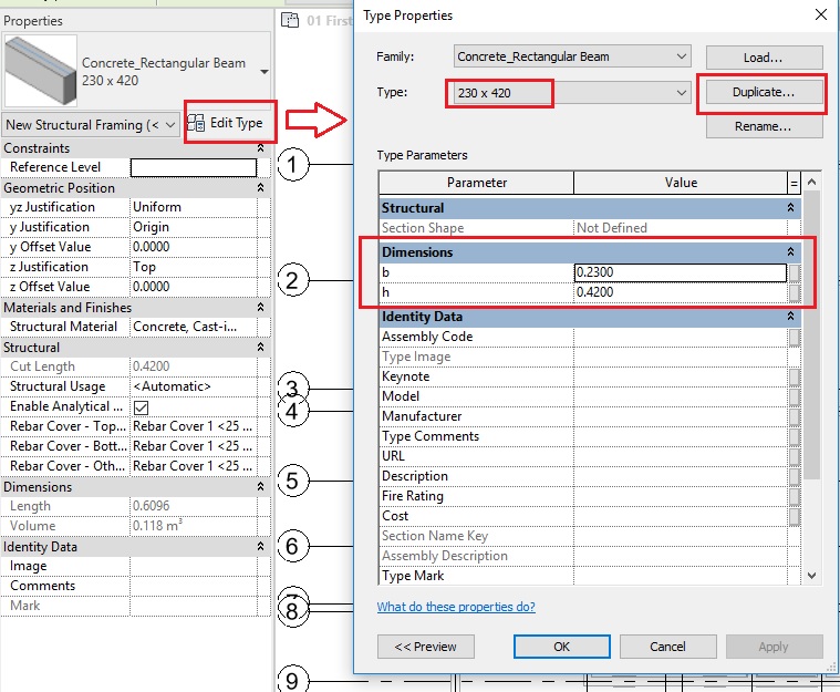
Concrete_Rectangular Beam: 230mm x 420mm placed as shown in Fig 1.
Sample Files required for this tutorial:
If you do not have the following files, please download them from here.
“TutorialBeams_Input_LearningRevitOnline.rvt”
Beam/Structural Framing Family files: “UB-Universal Beam.rfa” and “Concrete_Rectangular Beam.rfa”
Solution:
Open tutorial file ‘TutorialBeams_Input_LearningRevitOnline.rvt’ in Revit. This project file already contains levels, grids, walls and a column on ground floor level.
Navigate to the floor plan of “01 First Floor Level”. Ensure that you can see the ground floor layout as Underlay.
Underlay is like a sheet of drawing put underneath another to use as a reference. It helps in understanding the relationship of components at different levels for coordination and construction.
If you cannot see the Ground floor layout as an underlay, do the following.
To create an underlay:
In the Project Browser, open a plan view. (In this case, “01 First Floor Level”).
Go to the properties palette.
Go to the parameter “Range: Base Level” and select the level you want to underlay. In this case, select “00 Ground Level” as we want to see the layout of the Ground level as underlay.
“Range: Top Level” parameter is automatically set to one level above the Base Level. If you want to set a different level as the top range, select the level from here.
Ground level is now shown as underlay in halftone.
If you want to avoid mistakenly selecting the elements displayed in Underlay, you can turn off the “Select Underlay Elements”option on the status bar. Turn it on, if you want to select the elements in underlay.
Let’s first add structural steel beam of the “UB-Universal Beam” family between Grid B4 to C4 as shown in Fig 1.
Note: If you want to load a beam family from Autodesk content library, look for the required families under “Structural Framing” folder.
To add a structural beam/framing:
Go to Structure tab -> Structure panel -> Beam
Alternatively, use “BM” as the keyboard shortcut .
From the type selector, select the type 254x146x43UB of the UB-Universal Beam family you loaded in step 6.
On the options bar, select the Placement Level as First Floor Level.
On the options bar, select the structural usage of the beam as ‘Other’ . Revit will automatically assign this value based on which elements the beam is connecting.
In the drawing area, draw the beam from the grid intersection B-4 to C-4.
Click Esc twice to end the Beam tool.
As the beam is constructed under the first floor level (the top of beam matches with first floor level line), it is shown as an underlay element in halftone.
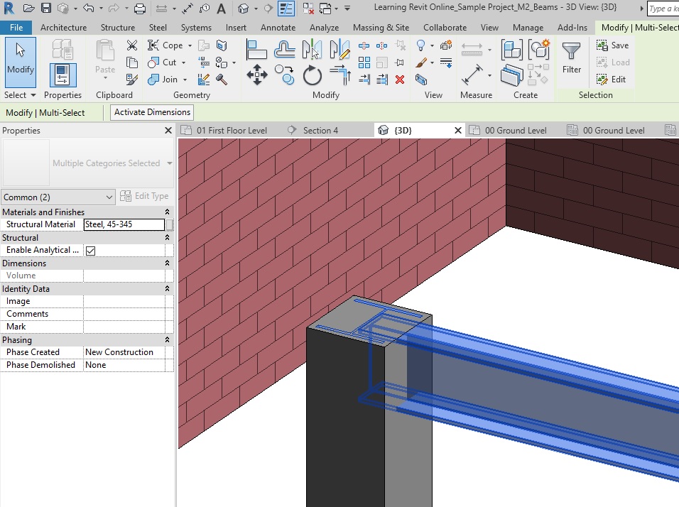
The beam, although added at the grid intersection B-4, may not extend upto the middle of the steel column. This is mainly because Revit has assumed the space for connections. However, if you would like to extend the beam to the center of the steel column, then select the beam.
Go to Modify|Structural Framing tab -> Join Tool panel -> Change Reference.
Select the face of the column that you would like the beam to connect to.
Click Esc twice to end the Modify tool.
TIP: Click and drag shape handles at the beam ends to adjust their end extensions or cutback. Learn more about how to use Shape handles here.
Go to a 3D view to visualize the output.
Now, let’s move on to add Concrete beam of “Concrete_Rectangular Beam” family as shown in Fig 1. Navigate back to the First Floor level floor plan and load the family “Concrete_Rectangular Beam.rfa” into the project.
Go to Structure tab -> Structure panel -> Beam
Alternatively, use “BM” as the keyboard shortcut .
From the type selector, select any one type of the Concrete_Rectangular Beam family you loaded in step 9.
Duplicate the existing type and create a new type of beam (named 230 x 420) that has width(b) = 230mm/0.23m and depth (h) = 420mm/0.42m
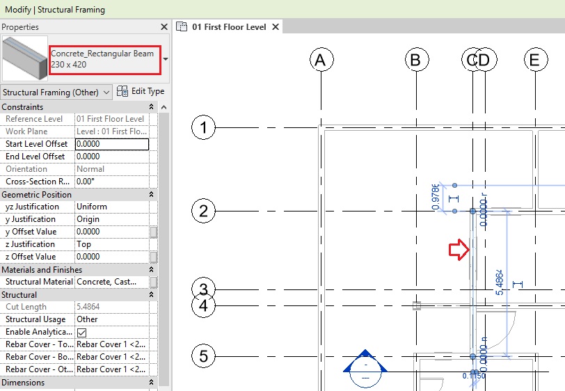
Repeat step 7, to add beams from Grid intersection C-2 to C-5.
Add a section line as shown below to see the beam in a section view.
Go to the section view and notice that the beam is added so that the top of the beam matches with the first floor level as required.
However, the walls and the beams are overlapping. In reality, the top of the wall shall match the bottom of the beam. One approach to resolve this is to use ” Join Geometry” tool. However, be careful with this tool as overusing it can use more memory and can cause unexpected issues, especially in large scale projects. The other approach is to use an offset value for the top constraint of the wall as shown below.
To adjust the height of the wall using offset values:
Select the wall.
Go to the Top Offset parameter in the Instance properties of the properties palette.
Add the value you would like to adjust. (In this case, as the beam depth is 0.42m and we want the wall to lower the value from the top constraint level, add offset value as “-0.42m” )
The wall height will adjust accordingly.
Now, notice that as this beam is not connected to structural columns, but instead it is on a wall, the wall shall also be a structural load-bearing wall. However, currently in the project, the wall is an architectural wall. You can see this by selecting the wall and checking its Structural Usage parameter in the Instance properties.
To convert architectural walls into structural walls:
Select the wall.
Go to its Structural parameters in the Instance properties.
Turn on the checkbox for the ‘Structural’ parameter.
Under Structural Usage parameter, select ‘Bearing’.
Now, the wall is converted to a structural load-bearing wall.
Note: You can avoid this step, if you already know from the beginning which walls are going to be structural walls. In that case, you can sketch walls using the tool:
Architecture tab-> Build Panel -> Wall Drop down menu -> Wall: Structural
Now, add more Concrete_Rectangular Beam family of 230×420 type in the project as shown in Fig 1. You may use Modify tools such as Trim/Extend to Corner or Trim/Extend to Single Element tools to create junctions between beams.
TIP: For more productive approach, instead of using Beam tool to sketch beams, use ‘Create Similar‘ tool. Using Create Similar tool makes your workflow more productive when you want to create more instances of the same type which you have already used once in the project. This saves you time to look for the right type of family in the type selector.
To use create similar tool, select the beam that you already placed -> go to create similar tool in Modify panel (“CS” as keyboard shortcut) -> the beam tool is active and the same type of beam has been selected in the type selector -> Now, you can begin adding beams as shown in step 7. To learn more about how to use create similar tool, click here.
TIP: When the Beam tool is active, on the options bar, turn on “Chain” option to add multiple beams in a continuous loop.
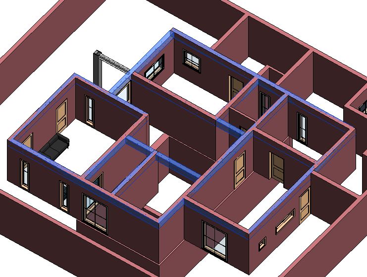
After adding all the beams as shown in Fig 1, go to a 3D view for a clear visualization.
Now, select all the walls that are under the beams. Repeat step 18 to adjust the height of the wall and step 20 to convert these walls into structural load-bearing walls.
TIP: While selecting multiple walls, press Ctrl to add walls to the selection and press Shift to remove walls from the selection.
TIP: Hover the mouse over one of the walls -> Press Tab to highlight the connected walls -> Click to select the highlighted walls.
TIP: To make the selection of multiple walls easier, you can also use Temporary Hide/Isolate tool to hide or isolate the walls and beams temporarily.
Temporary Hide/Isolate tool:
To isolate category temporarily:
Select one of the element for which you would like to isolate the category.
In this case, select one of the walls and one of the beams.
Go to View Control bar -> Temporary Hide/Isolate -> Isolate Category.
All the beams and walls in the view will be isolated.
To hide elements temporarily:
Select the elements that you wish to hide.
Go to View Control bar -> Temporary Hide/Isolate -> Hide Element
The selected elements will be hidden.
To reset Temporary Hide/Isolate view:
Go to View Control bar -> Temporary Hide/Isolate -> Reset Temporary Hide/Isolate
After adjusting the wall height and their structural usage, go to a 3D view to see all the beams you have added.
After completing all the steps above, Save As your project as ‘TutorialBeams_Output_LearningRevitOnline.rvt’.
As their name suggests, use the structural columns to add load-bearing vertical elements to the model and use architectural columns to add decorative vertical elements. Structural elements such as beams, braces, and isolated foundations join to structural columns; they do not join to architectural columns.
Add an architectural column surrounding the structural column on Grid B-4 in the Ground Floor layout as shown below.
Height of both columns: Ground Level to First floor level
Structural Column: UC-Universal Column Type 254x254x73UC
Architectural Column: Architectural-Column-Rectangular type 300 x 300
Sample Files required for this tutorial:
If you do not have the following files, please download them from here.
“TutorialColumns_Input_LearningRevitOnline.rvt”
Column Family files: “UC-Universal Column.rfa” and “Architectural-Column-Rectangular.rfa”
Solution:
Open tutorial file ‘TutorialColumns_Input_LearningRevitOnline.rvt’ in Revit. This project file already contains levels, grids and walls on ground floor level.
Click Insert tab -> Load from Library panel -> Load Family -> Navigate to the folder where above families are located on your computer -> Select them -> Open.
To place a structural column:
Go to Structure tab -> Structure panel -> Column
Alternatively, use “CL” as the keyboard shortcut .
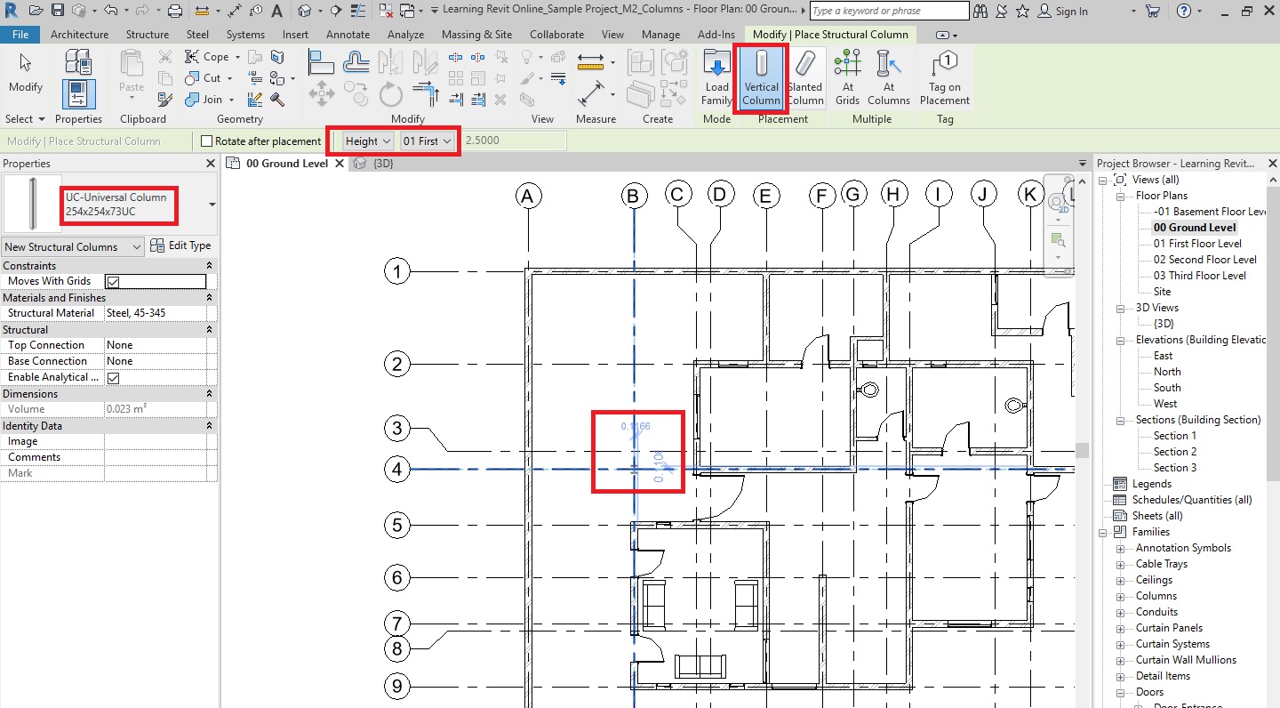
From the Modify|Place Structural Column tab , select vertical column.
From the type selector, select the type 254x254x73UC of the UC-Universal Column family you loaded in step 3.
On the options bar, select the Height and constraint it to First Floor level.
In the drawing area, notice that column’s center automatically tries to snap at the grid intersections. Click at the grid intersection B-4 to place the column.
Click Esc twice to end the Column tool.
Now, we would like to place a rectangular architectural column that surrounds the structural column that we placed in step 4.
To place an architectural column:
Go to Architecture tab -> Build panel -> Column drop-down -> Column: Architectural
From the type selector,select the type 300 x 300 of the Architectural-Column-Rectangular family you loaded in step 3.
If you do not have this type, create a new type by duplicating the existing one and changing the width and height value of the type parameters to 300mm.
On the options bar, select the Height and constraint it to First Floor level.
On the options bar, select the ‘Room bounding’ option. This will ensure that the boundary of the column is part of the boundary of the room along with other room bounding elements when you create a room.
In the drawing area, notice that column’s center automatically tries to snap at the grid intersections. Click at the grid intersection B-4 to place the column.
Click Esc twice to end the Column tool.
Now, we have a structural column that is surrounded by an architectural column.
Go to a 3D view to see these columns in a 3D.
After completing all the steps above, Save As your project as “TutorialColumns_Output_LearningRevitOnline.rvt”.
More about Columns:
How to Attach Columns with roofs, floors, ceilings, reference planes, structural framing members, isolated foundations, foundation slabs, and other reference levels.
Components are those building elements that are usually delivered and installed on site – such as furniture, plumbing fixtures, lighting, etc. Components are loadable families, which need to be loaded in the project from your content library.
There are free standing components such as furniture or equipment placed on a floor/level. There are also host-based components which are dependent on a building element that acts as a host such as a wall lamp that has wall as its host. When a wall is moved/deleted, the dependent component is also moved/deleted. Usually, the wall, floor, level/work-plane, roof, ceiling or a face of an object work as a host for components.
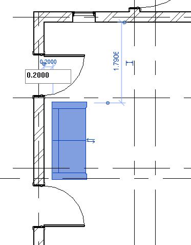
Add 3 instances of Furniture_Sofa.rfa and 2 instances of Plumbing_WC.rfa components to the Ground Floor layout as shown in Fig 1.
Fig 1. Placement of components in the Ground Floor layout of the sample project
Sample Files required for this tutorial:
If you do not have the following files, please download them from here.
“TutorialComponent_Input_LearningRevitOnline.rvt”
Component Family file: “Furniture_Sofa.rfa” and “Plumbing_WC.rfa”
Solution:
Open ‘TutorialComponent_Input_LearningRevitOnline.rvt’ in Revit. This project file already contains doors and windows modeled in the Ground Floor levels.
Click Insert tab -> Load from Library panel -> Load Family -> Navigate to the folder where above families are located on your computer -> Select them -> Open.
To place a component:
Go to Architecture tab -> Build panel -> Place a Component
Alternatively, use “CM”as keyboard shortcut.
Select the type for the Furniture_Sofa family from the Type selector.
In the drawing area, place the sofa as shown below. Press Spacebar to change the orientation of the sofa. Do not worry about the exact position at the moment which can be adjusted after the sofa has been placed.
Click Esc twice to end the Components tool.
Click on the Sofa that you have placed. Temporary dimensions will appear. Use these dimensions to locate the sofa 0.2m away from the edge of the wall behind it.
Now, position the sofa exactly in the middle of the Grid 5 – 9 by using equality constraint as shown below.
To learn how to use equality constraint, click here.
Repeat step 4-6 to place two more instances of sofa as shown below.
Let’s now, place a WC in the toilet, which is a host-based (dependent on the wall) component.
To place a host-based component:
Ensure that you have already loaded the family Plumbing_WC in your project.
Go to Architecture tab -> Build panel -> Place a Component
Alternatively, use “CM”as keyboard shortcut.
Select the type for the Plumbing_WC family from the Type selector.
In the drawing area, notice that you cannot place this component anywhere. If you take your cursor to a wall, only then you are able to place this component as it requires the wall as its host.
Click on the wall on Grid-G as shown below to place the WC in its position.
Click Esc to end the component tool.
Select the WC after placing it. Using the temporary dimensions, adjust the position of the WC to be 0.5m away from the inner face of the wall on Grid 2 as shown below.
Click Esc to deselect the component.
Now, let’s create one more instance of the same type of WC in another toilet area of the project as shown below. However, instead of using a Component tool, you can use “Create Similar” tool to be more efficient.
To use create similar tool:
As you want to make more instances of the same type of family, select the instance already in the model.
Go to Modify tab -> Create panel -> Create Similar ( OR “CS”as keyboard shortcut). If you have selected a component, Component tool will be active and the same type from the type selector will be automatically selected.
Now, you can continue to place more instances of the same type.
Create similar tool works across all Revit elements (ex. walls, grids, doors, etc), it immediately activates the tool required to create another instance of the same type selected of that particular family. Adds wonders to your productivity !!
Adjust the position using temporary dimensions as required after placing the component.
After placing a host-based component, if you would like to move it another host, Move tool will not be very effective. Instead, use “Pick New Host”tool.
To move a host-based component to a different host:
Select the component you want to move.
Go to Modify tab -> Host panel -> Pick New Host tool.
Select a different host element for the component and place it at the required position.
Note: If the component is wall-based, you can only select a new host for that component to be a wall. It cannot be placed to a different category of host for which it has not been created.
Click Esc to end the Pick New Host tool.
After completing all the steps above, Save As your project as “TutorialComponent_Output_LearningRevitOnline.rvt”.
More References:
Some of the popular online libraries to download Revit components are: