About Floors
Floors are defined in Revit by boundaries either sketched using drawing tools or by picking walls. Floors are created downwards from the level on which they are sketched. Thus, by default, top of the floor is aligned with the level line.
You create floors by defining their boundaries, either by picking walls or using drawing tools.
Tutorial Objective:
In this tutorial, you will learn,
- To add a structural floor slab
- To create a new floor type with required thickness
- To Copy and Paste Align
Sample Problem:
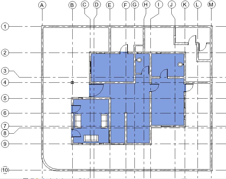
Create a structural floor slab with boundary as highlighted in Fig 1, at “00 Ground Level” and “01 First Floor” of the sample project. The floor slab shall be 100mm thick and of Concrete Material.
Sample Files required for this tutorial:
If you do not have the following files, please download them from here.
- “TutorialFloors_Input_LearningRevitOnline.rvt”
Solution:
- Open the tutorial file ‘TutorialFloors_Input_LearningRevitOnline.rvt’ in Revit. This project file already contains walls on Ground level.
- As we want to create a floor under the Ground level, navigate to the floor plan of “00 Ground Level”.
- As this would be a structural floor/slab, we will use Structural Floor tool.
- To create non-structural floors, use Architectural floors (Architecture tab -> Build panel -> Floor drop-down ->Floor: Architectural)
To add a structural floor slab:
- Go to Structure tab -> Structure panel -> Floor drop-down -> Floor: Architectural
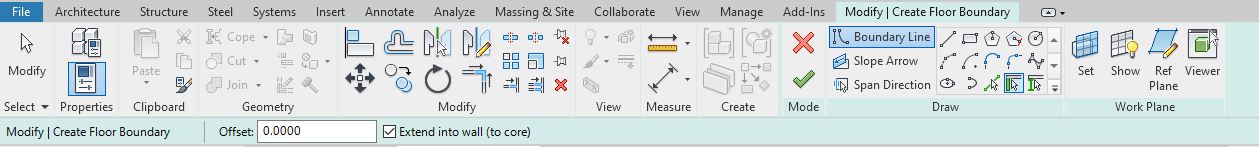
- Revit will enter into a Sketch mode. The tab ‘Modify|Create Floor Boundary’ will become active.
- Select the type of floor you would like to create from the Type Selector. For this tutorial, select ‘Generic 150mm’.
- To manually sketch the boundary, you can use the drawing tools available in the Draw panel. But, as the walls are already available in the layout which define the floor boundary, we will use “Pick Walls” tool.
- Pick walls that define the boundary of the floor in the drawing area as shown below.

- TIP: As you pick walls, the flip arrows will appear on the line. Use this flip arrow to flip the line between the inner and outer boundary of the wall.
- In a sketch mode, no lines can overlap or intersect each other. Use modify tools such as Trim/Extend to make a closed loop as shown below.

- After drawing the boundary, click Finish Edit Mode to end the Sketch mode.
- Revit may give you a notification whether you would like to attach the highlighted walls to the floor. For now, select No.
- Note: If the floor moves in elevation, attached walls will adjust their height accordingly. Select ‘Yes’ if you want this effect to happen. Select ‘No’ if you do not want this to happen.

- Note: If the floor moves in elevation, attached walls will adjust their height accordingly. Select ‘Yes’ if you want this effect to happen. Select ‘No’ if you do not want this to happen.
- Go to a Section view to see the Floor. Notice that the top of the floor is aligned with the ’00 Ground Level’.

- Thickness and Material of the floor are defined by the type property of the floor. Thus, you may choose a required type of the floor from the type selector before creating the floor or you can select the floor after modeling and change its type from the type selector.
- If you do not have the type of floor you require in the type selector, you can create a new type and adjust the thickness of the floor.
To create a new floor type with required thickness:
- Select the floor you would like to change the type for.
- For this tutorial, select the type “Generic 150mm”.
- Go to the Properties palette -> Edit Type -> Duplicate -> Rename the new type of floor (for example, ‘100mm Concrete Slab’)

- Say OK after naming the type.
- Under Type parameters -> Go to Construction parameter group -> Structure Parameter -> Click Edit.
- Edit Assembly dialog box will appear.
- Add the values for thickness as 100mm /0.1m
- Click to change the value of the material. To open the material browser, click on the “…” sign in the cell.
- Select Concrete as the material for this layer.

- Click OK to the material browser.
- Click OK to the Edit Assembly dialog box.
- Click OK to the Type properties.
- The selected floor has now changed from ‘Generic 150mm’ type to ‘100mm Concrete Slab’ type of floor. The thickness and the material both have been changed for this floor.
- NOTE: To create a floor with multiple layers, please refer the tutorial ‘Compound Structures‘
- Select the floor you would like to change the type for.
- Often in a multi-level building, floor boundaries remain the same across levels. You may choose to copy or array the floors from a section view. Another efficient way for doing this is to use Copy with ‘Paste Aligned’ function. Using this function ensures that position of the copied element is aligned exactly at each level. This way, manual errors are reduced while copying.
To Copy and Paste Align:
- Select the element from any view.
- Using ‘Ctrl+C’, copy the element on clipboard.
- Go to Modify tab -> Clipboard panel -> Paste Drop down -> Aligned to Selected Levels

- Select the levels you wish to copy at.
- Press Ctrl to add to the selection, Press Shift to remove from the selection.

- Press Ctrl to add to the selection, Press Shift to remove from the selection.
- Say OK to Select Levels dialog box.
- Element will be copied on the selected levels.
- Using Copy and Paste align tool as shown in the step above, copy the floor on Ground level that you created in step 5 and paste align it on First floor level.
- Go to a 3D view to see both slabs in 3D.

- TIP: If required, use Temporary Hide/Isolate tool for clarity of view.
- After completing all of the steps above, Save As your file as ‘TutorialFloors_Output_LearningRevitOnline.rvt’
More References:
- Create a Sloped Surface Using a Slope Arrow
- Edit a Floor boundary after modeling
- Add a Floor Slab Edge
- More about sloped surfaces
- To create a floor with multiple layers, learn more about ‘Compound Structures‘.
- Basic Modify Tools
