About Windows
Windows can be added in plan, elevation, section or a 3D view. Windows are loadable families, which means that the family of the Window (sizes, shapes, design) can be customized and placed in the library to load them in your project.
Windows are dependent elements on their host which is usually a wall. Like in real life, a window cannot be placed if there is no wall on site. Similarly, in Revit, a Window cannot be placed without a wall.
Tutorial Objective:
Modeling windows is similar to modeling doors. Thus, it is recommended that you familiarize yourself with tools and techniques shown in the chapter Modeling Doors before starting this tutorial.
In this tutorial, you will learn,
- To load a family into the project
- To customize the window sizes and create new window types
- To place a window in the project
- To add Window Tags on your drawing
Sample Problem:
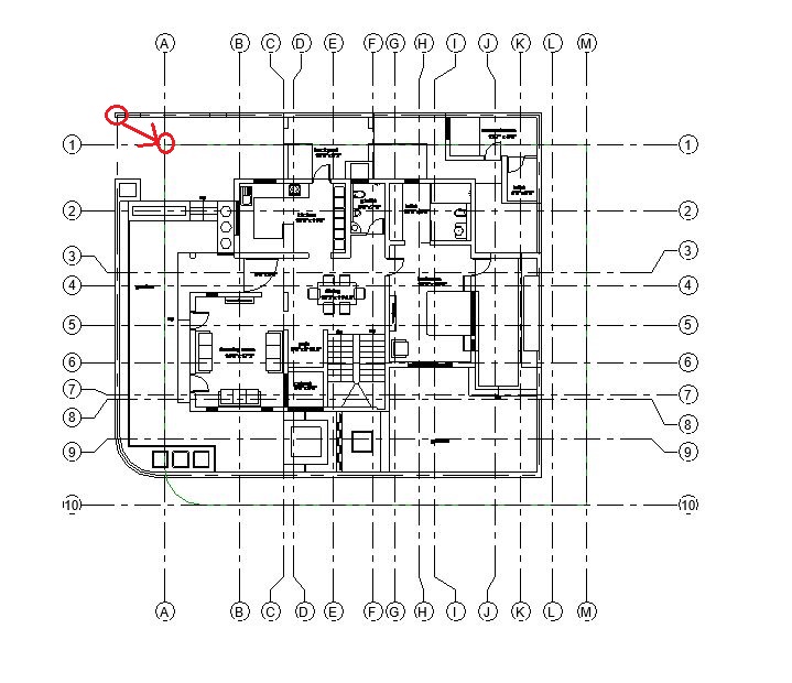
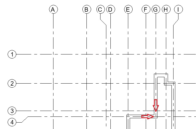
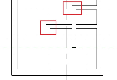
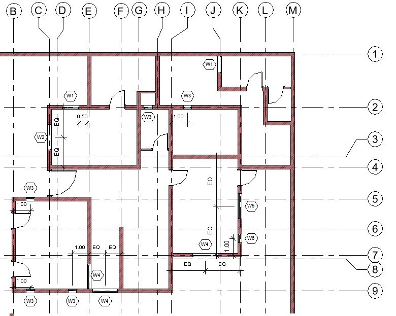
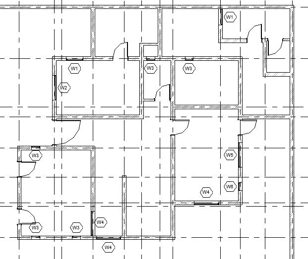
- Add windows of following types in the Ground Floor layout as shown below:
- W1: 1.0 x 1.0 m (Lintel Height: 2.13m)
- W2: 1.5 x 1.0 m (Lintel Height: 2.13m)
- W3: 0.5 x 2.0 m (Lintel Height: 2.13m)
- W4: 1.5 x 2.0 m (Lintel Height: 2.13m)
- W5: 1.5 x 0.5 m (Lintel Height 1.6m)
- W6: 0.5 x 0.5 m (Lintel Height 1.6m)
Sample Files required for this tutorial:
If you do not have the following files, please download them from here.
- “TutorialWindows_Input_LearningRevitOnline.rvt”
- Window Family file: “Window_Single Panel.rfa”
- Window Tag Family file: “Window_Type Tag.rfa”
Solution:
- Open ‘TutorialWindows_Input_LearningRevitOnline.rvt’ in Revit. This project file already contains doors modeled in the Ground Floor levels.
- Navigate to the floor plan of “00 Ground Level”.
- Windows are loadable families which means we will first need to load the family of the window from the library (if it is not already loaded in your project).
-
To load a family into the project:
- Click Insert tab -> Load from Library panel -> Load Family
- Navigate to the folder where you have downloaded and saved the Window_Single Panel.rfa (If you do not have this file yet, please download it from here).
- Note: By default, Revit will navigate to the library where default Autodesk families are stored. If you do not find this path when you need it, try to locate it on your PC at : %ALLUSERSPROFILE%\Autodesk\RVT 2019\Libraries (If you cannot still find the location of your family library, please see this Video Tutorial: Locating your family folder )
- Select the file and Click Open.
- The family has been loaded into the project.
- Now, before we add the windows into our model, we must create the Window types with the specific sizes as required for our project.
-
To customize the window sizes and create new window types:
- Click Architecture tab -> Build panel -> Window
- Alternatively, use “WN”as keyboard shortcut.
- From the type selector, select any of the types available for Window_Single Panel family.
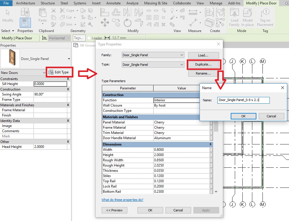
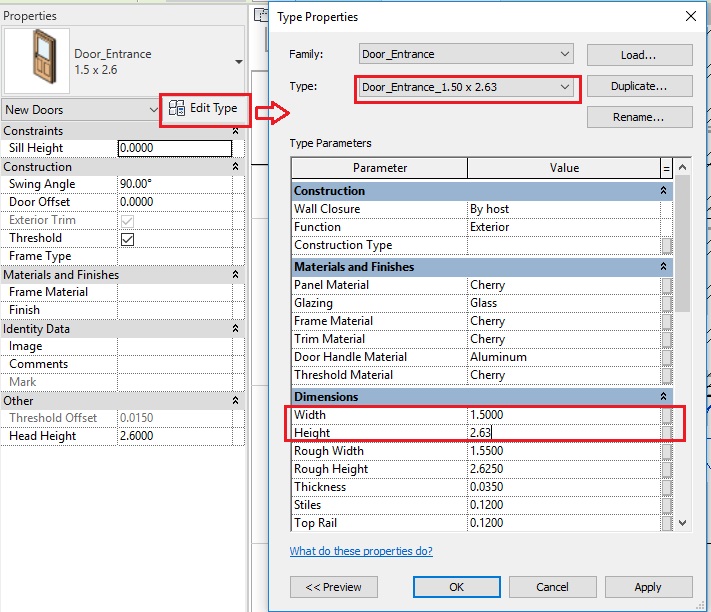
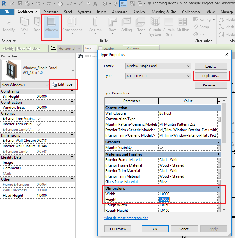
- From the properties, select Edit Type to access Type properties palette.
- Click Duplicate to create a new Window Type. In the Name dialog box, give a new name to the window type “W1_1.0 x 1.0”
- Click Ok to the Name dialog box.
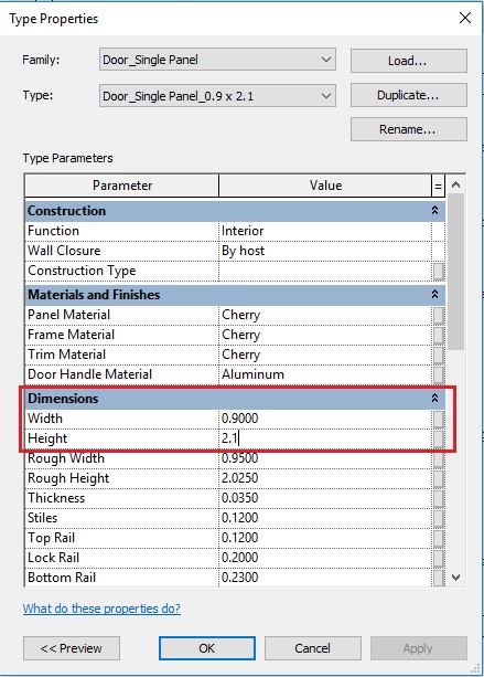
- Now, change the parameters Width to 1.0m value and Height to 1.0m value.
- Click OK to the Type Properties dialog box.
- A new window type has been created.
- Click Esc to end the Window tool.
- Click Architecture tab -> Build panel -> Window
- Repeat step 6 to create following window types:
- W2_1.5 x 1.0 (width = 1.5m, height = 1.0m )
- W3_0.5 x 2.0 (width = 0.5m, height = 2.0m )
- W4_1.5 x 2.0 (width = 1.5m, height = 2.0m )
- W5_1.5 x 0.5 (width = 1.5m, height = 0.5m )
- W6_0.5 x 0.5 (width = 0.5m, height = 0.5m )
- Now, as all the window types required are prepared, we can begin to place windows in the model.
-
To place a window in the project:
- Click Architecture tab -> Build panel -> Window
- Alternatively, use “WN”as keyboard shortcut.
- Select the Window type W1_1.0 x 1.0 from the type selector.
- Select the window. In the Instance properties, there is parameter known as “Head Height”. This parameter value control the lintel height of the window. Change the value of head height to 2.13m (Note that when you change the value of the Head height, Sill height parameter will change automatically based on the Height of the window selected).
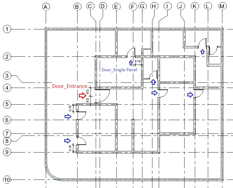
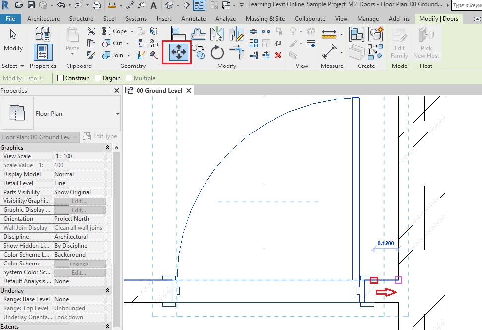
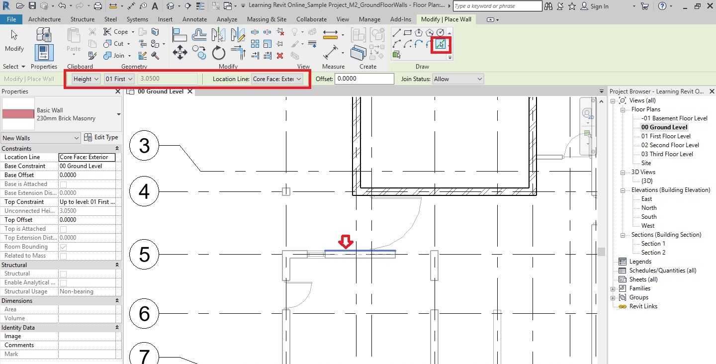
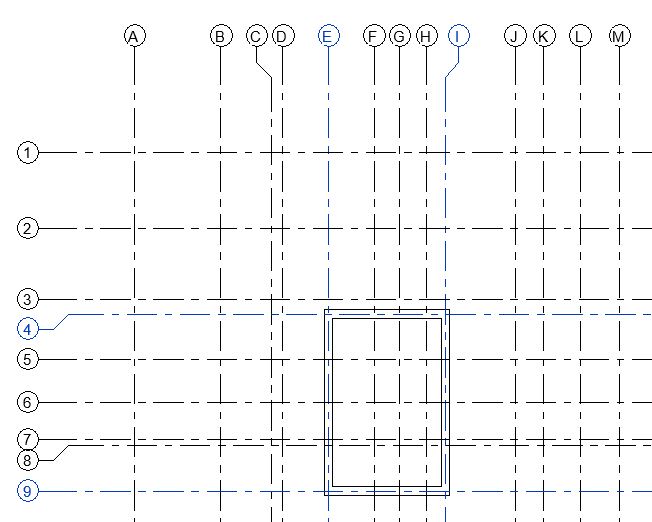
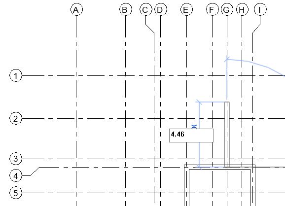
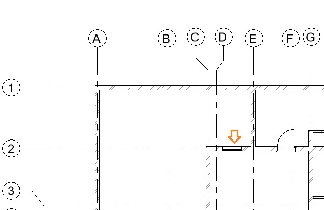
- In the drawing area, click on the wall where you would like to place the window (between Grid D2-E2 as shown below). Do not worry about accurate position at the moment. You can adjust it after you have placed the window.
- TIP: Press the Spacebar to flip the window while placing it in plan view.
- Click Esc twice to end the Window tool.
- Note that after placing the window, Revit has made an appropriate opening in the wall automatically.
- Click Architecture tab -> Build panel -> Window
- Select the window you have placed.
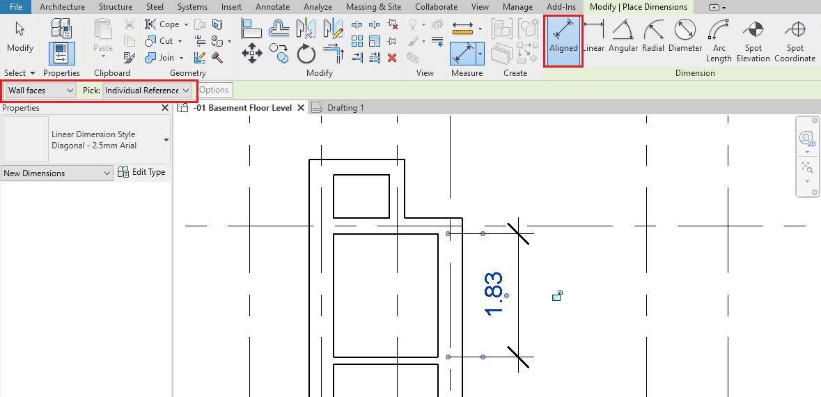
- Temporary dimensions will appear. If they do not appear, click on “Activate Dimensions” on the options bar.
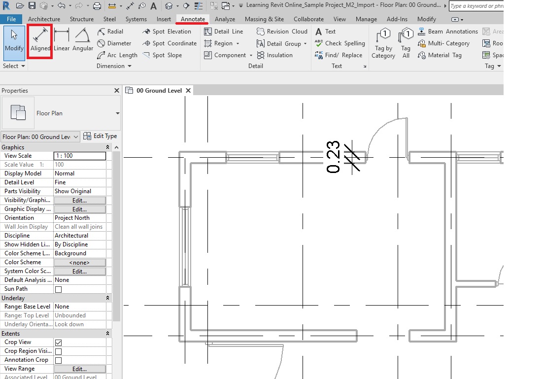
- TIP: You can also use a permanent dimension (Annotate->Dimension->Aligned Dimension) instead. Select the window and the permanent dimension will be editable. If it is not editable, select Activate Dimensions to make it editable.
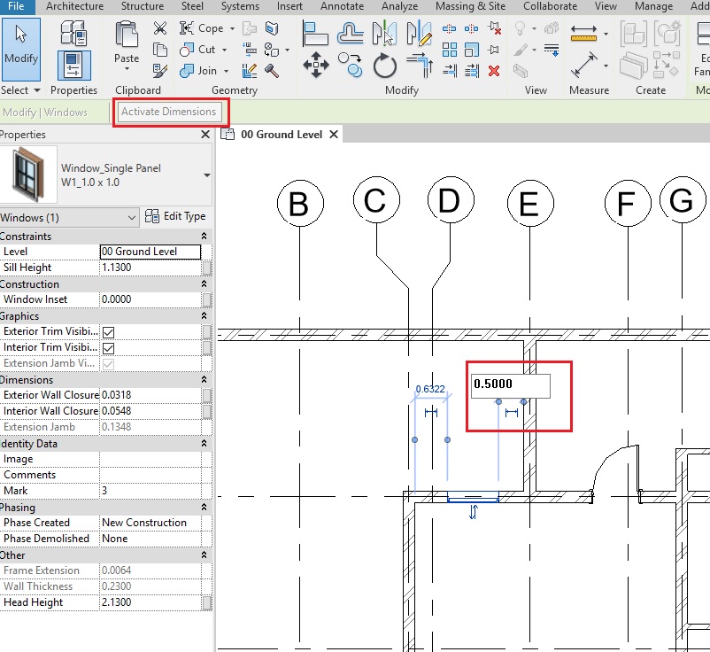
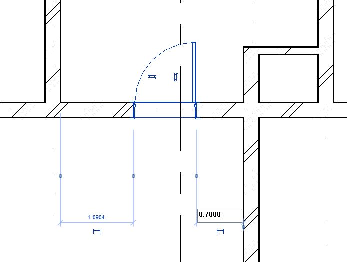
- Change the value of the temporary dimension to 0.5m from the right edge of the window to the face of the wall on Grid E as shown above. Use the Witness line controls (blue dots on the temporary dimensions) to adjust the reference of the dimension, if needed.
- TIP: Alternatively, you can also place a permanent dimension between the window and the wall. Select the window after placing the dimension and change the value of the dimension. (If the dimension is non-editable, click on Activate Dimensions to activate it).
- Now, let’s place another instance of the W1_1.0 x 1.0
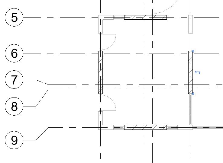
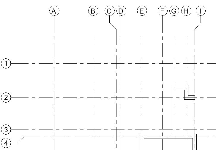
- Repeat step 9 to place the window at Grid J as shown below.
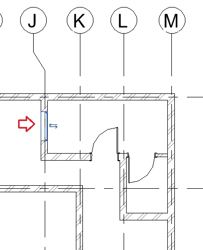
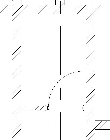
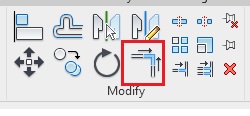
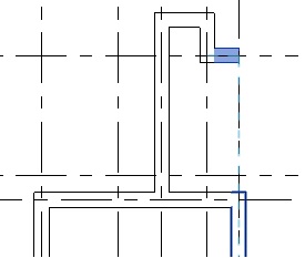
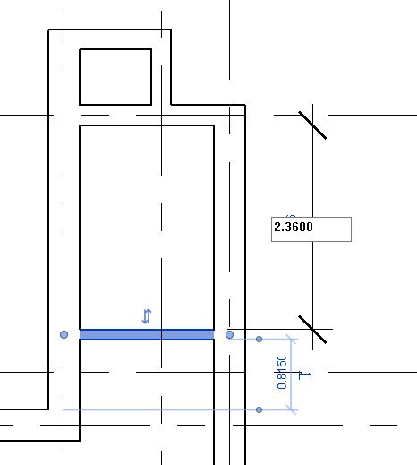
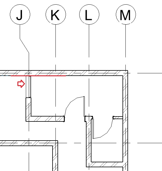
- Using the Align tool (Modify tab -> Modify panel -> Align), align the edge of the left face of the window to the inner face of the wall as shown below.
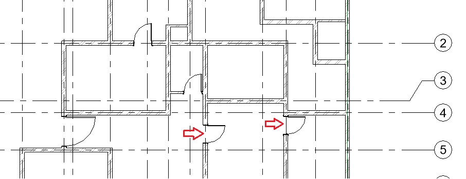
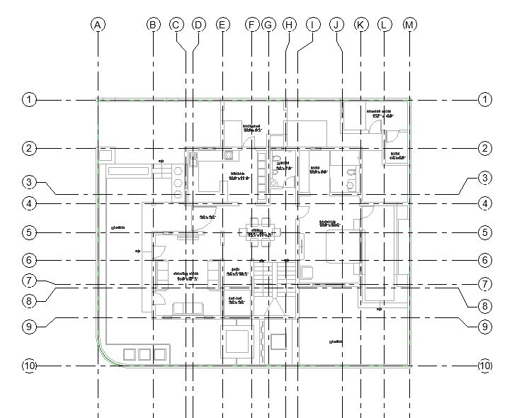
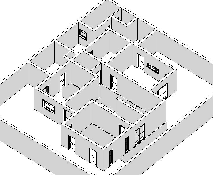
- Repeat Step 9 to add other windows as shown in Fig 1. Ensure that the head height for windows is 2.13m for window type W1, W2, W3, W4 and 1.60m for window type W5 and W6.
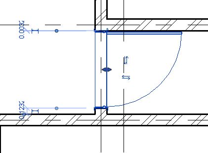
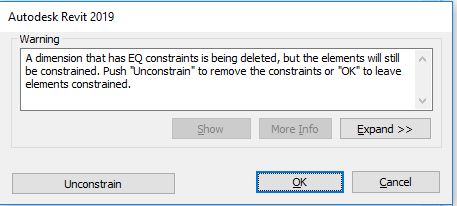
- Use tools such as Align and Move to position the windows correctly. You may also use temporary, permanent dimensions and equality constraints to position the windows at a specific distance from other elements. Learn more about these tools in the chapter Modeling Doors
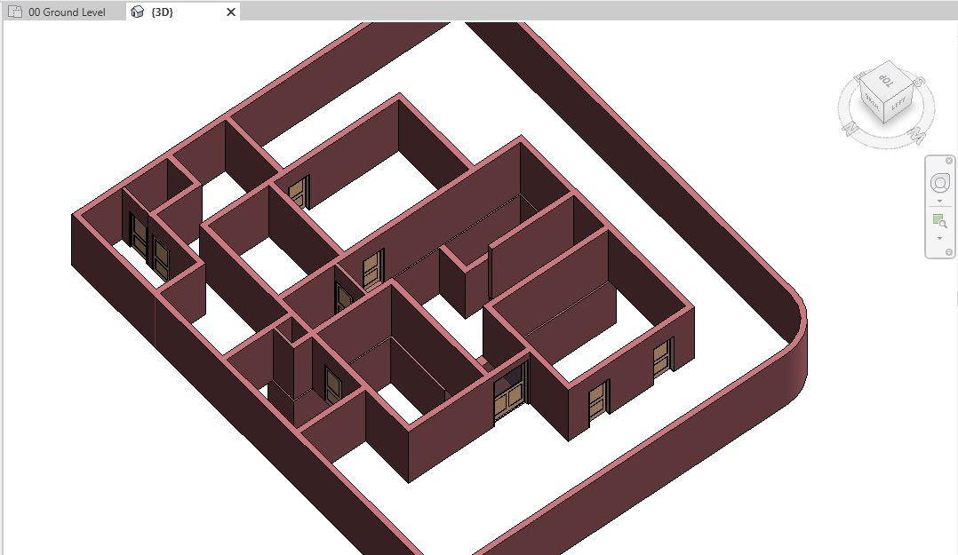
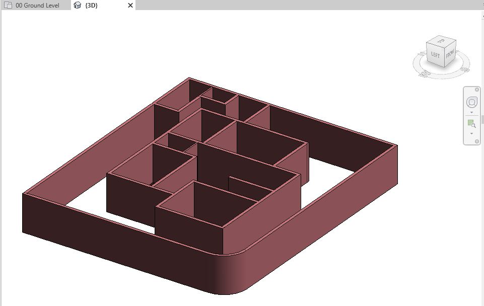
- Now, after modeling all windows, navigate to a 3D view to see all the windows in 3D.
- After adding all the windows, let’s now add annotation of the window type numbers as window tags in the drawing as shown in Fig 1.
-
To Add Window Tags on your drawing:
- Window tag is a 2D annotation family that needs to be loaded into the project. Repeat step 4 to load the family “Window_Type Tag.rfa“
- Go to Annotate tab -> Tag panel -> Tag All
- The ‘Tag All Not Tagged’ dialog box will appear where the loaded Window_Type Tag family is listed. Select this tag by turning on the checkbox besides its name.
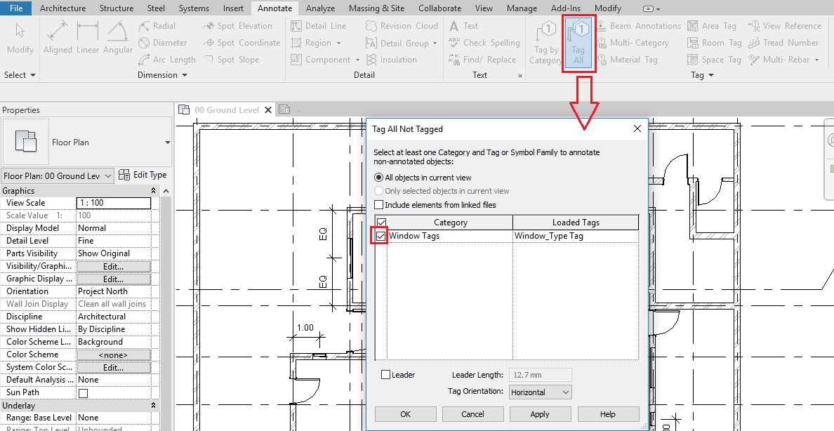
- Say OK.
- Tags for all windows will be added in the drawing.
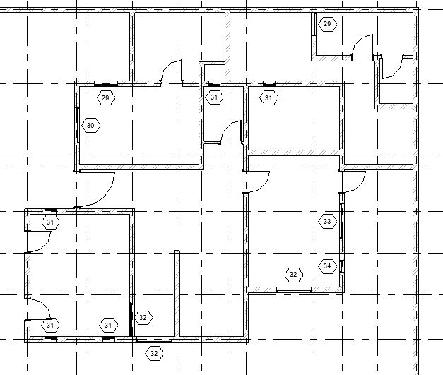
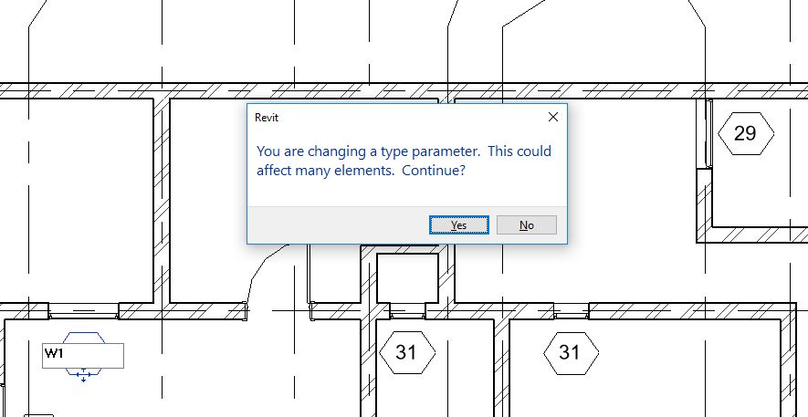
- Each window type has been assigned a Type mark which is displayed here. However, the numbering done by Revit may not be as per your specifications. To change the Type mark value of the windows, select the tag and click on its text. Change the value as per your need.
- When you change the value, Revit will display a warning that if you change a value in the type parameter, all instances of that type will reflect that change. Say Yes to apply this change.
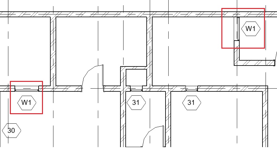
- You will see that all the tags of the same window types now reflect the change.
- An alternative method to change the type mark of windows is to change the value in the Type properties of the windows.
- Click Architecture tab -> Build panel -> Window
- From the Type selector, select the window type you want to apply the change. Go to Edit Type and open the Type properties palette.
- Change the value in the Type Mark parameter.
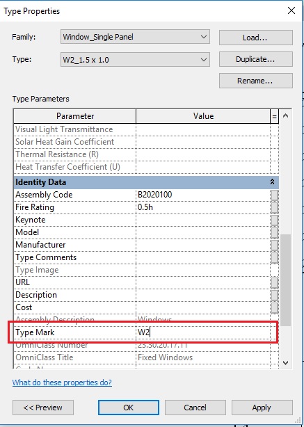
- Click Apply.
- Now select another Type of window in the TYPE field of the type properties palette and change its Type Mark value as required. Click Apply. Repeat this step till you have changed Type mark of all windows.
- Click OK to the Type properties palette.
- Click Esc to end the window tool.
- Note that all window tags now reflect the changes you have made.
- After completing all the steps above, Save As your project as “TutorialWindows_Output_LearningRevitOnline.rvt”.
More References:
- Learn more about why sometimes temporary dimensions are not displayed in Revit.
- After placing the window, if you would like to move it to another wall, use ‘pick new host’ tool to move the window.
- Video Tutorial: Create a custom tag presented by josukke
- If your project requires a different numbering system or if you wish to customize window tags as per your project specifications, you can create your own custom window tag family.
- Video Tutorial: How to create a window family presented by SmarterArchitect.
- If you would like to create your own custom family for the window, it is advised that you first familiarize yourself with basic family editing tools covered in later sections of this course. However, if you are already familiar with them, you can create a custom window as guided by this tutorial.