Grids are Datum elements used for marking the alignment for the structural elements (columns/structural walls) in a building design. Grids consist of Grid line and Grid symbol. Grid lines can be controlled from Grid properties. Grid symbols can be customized by creating a custom Grid head family.

Video Tutorial

Learn about how to add grids to the project with this Video Tutorial – by Autodesk Building Solutions

Step by Step Guide

Practice Tutorial

If you would like to further practice your skills with Grids, please use the Practice Tutorial below where you will learn to,

  • Add a new Grid
  • Offset Grids
  • Copy Grids
  • Add Grid symbols to both sides
  • Offset Grid symbols

PRACTICE TUTORIAL available here – “Practice adding Grids”

Q&A

Have any Questions? or Suggestions? or Feedback? Please feel free to Contact Us, we will get back to you as soon as we can.

Create Grids

Use the Level tool to define a vertical height or story within a building. Levels can be added or edited in a vertical view (either elevations or sections).

If you already have information about all the building story levels in your project, you may very well create them before you begin a project. If there are any changes later in the project, you can always come back and make these changes. In case, if you do not have information about all the levels, then it is necessary that you create at least one building story to begin your project. This makes it easier to attach your walls and other building elements to the levels.

Video Tutorial

Step by Step Guide

Practice Tutorial

If you would like to further practice your skills with levels, please use the Practice Tutorial below where you will learn to,

  • Rename a Level
  • Change the elevation height of a Level
  • Create a new Level
  • Copy a Level
  • Create a floor plan view

PRACTICE TUTORIAL available here – “Practice defining Levels”

Q&A

Have any Questions? or Suggestions? or Feedback? Please feel free to Contact Us, we will get back to you as soon as we can.

Create Levels

Tutorial: Roof

About Roof

You can create a roof in Revit using mainly the “Roof by Footprint” and “Roof by Extrusion” methods. Different shapes of roofs can also be developed using combination of both of these methods. To create dynamic shapes of roofs, “Roof by Face” method along with Massing can be used. 

Tutorial Objective:

In this tutorial, we will be learning the ‘Roof by Extrusion’ approach. To learn more about other methods to create Roof, use the resources here. In this tutorial, you will learn,

Sample Problem:

Create a 100mm thick concrete roof at 30 degree angle between Grid 6-9 and Grid E-F in the sample tutorial project as shown in Fig 1 and 2 below.
M2 Roof Tutorial

Fig 1. Sloped Roof in the sample tutorial project

M2 Roof Tutorial 1

Fig 2. Sloped Roof in the sample tutorial project

Sample Files required for this tutorial: If you do not have the following files, please download them from here.
  • “TutorialRoof_Input_LearningRevitOnline.rvt”

Solution:

  1. The tutorial file “TutorialRoof_Input_LearningRevitOnline.rvt” already contains basic model of the building.
  2. Navigate to the floor plan of “02 Second Floor Level”.
  3. To create a the profile of the roof as shown in Fig 1 above, we will use ‘Roof By Extrusion’ approach.
    • NOTE: Roof By Extrusion is an efficient approach when a cross-sectional profile of the roof is known. The width of the roof can be determined by the depth of extrusion for the roof. 
  4. To create a roof by extrusion method:

    • Click Architecture tab -> Build panel -> Roof drop-down -> Roof by Extrusion
    • Now, the next step is to draw a cross-sectional profile defining the shape of the roof. To draw in a vertical plane, we will need to define the workplane for the cross-section.
      • To learn more about work-planes and how to use them, click here.
    • Revit will open workplane dialog box where you can either pick a plane or specify one. As the cross-section of the roof lies between Grid E-F, we can pick one of these Grids graphically (Pick a plane option) or we can choose one of them by name as shown below.M2 Roof 1
    • Click OK.
    • As this workplane is a vertical plane, Revit will ask you to open one of the vertical views such as elevation or section. Choose the Section FF which is already placed in the project.
    • Roof Reference Level and Offset dialog box will open. This will define the level that the roof will be connected to. Choose the “02 Second Floor Level”. 
    • Now, you are ready to draw the cross-section profile.
    • Go to the tab ‘Modify|Create Extrusion Roof Profile’ -> Draw panel -> Choose Line as a drawing tool.
    • Draw a line at 30degree angle as shown below.
      • NOTE: Extrusion profiles need to be open (not a closed-loop). Thickness to the profile is given by the Roof Type.M2 Roof 2
    • Go to the properties palette -> Type selector -> choose RCC 100mm roof type.
      • You can opt to Duplicate the type and edit the thickness, materials and layers of the roof. To learn more about layers in a compound structure, click here.
    • Go to the tab ‘Modify|Create Extrusion Roof Profile’ -> Mode panel -> Finish Edit Mode.
    • The Roof has been created. Now, let’s adjust the width of the roof in a plan view.M2 Roof 3.JPG
    • Go to ’02 Second Floor Level’ floor plan view.
    • Select the roof. 
    • Notice the Extrusion Start and End parameters in the properties palette. Extrusion start with 0.00 value is located at the workplane. You can adjust these values to adjust the width of the roof. Alternatively, you can also drag the control arrows at the roof edges to adjust the extrusion width.
      • Use Align tool to quickly align the extrusion start and end edges to the desired location.M2 Roof 4
    • Ensure that the roof is aligned with outer edges of the wall as shown in the picture above.
    • The roof is now created.
  5. Go to a 3D view to see the roof clearly.
  6. Note that the wall on grid E is extending beyond the roof. You can adjust this by attaching the wall to the roof. This will allow the wall to automatically take the shape of the roof when it attached to it.M2 Roof 5.JPG
  7.  To attach a wall to the roof:

    • Select the wall that you wish to attach.
    • Go to the tab ‘Modify|Walls’tab -> Modify wall panel -> Attach Top/BaseM2 Roof 6.jpg
    • Select the roof with which the wall needs to attach.
    • Notice that the wall is not attached and has taken the shape of the roof profile.
      • When you detach the wall from this roof, the wall will automatically switch back to its original profile.M2 Roof 7.JPG
  8. Navigate to Section FF. 
  9. Notice the overlapping join between the roof and the beam. If you would like to clean this join, use ‘Join Geometry‘ between these two elements.M2 Roof 8.jpg
  10. After completing all of the steps above, save as the project as, “TutorialRoof_Output_LearningRevitOnline.rvt”  

More about Roofs:

Tutorial: Beam system

About Beam System

Beam system is a tool to add additional support to the main structural frame in the form of cross-beams. You use beam systems to fill structural bays with beams to help support floors or ceilings in a structural model. Beam systems are also useful for laying out rafters for wooden roofs.

Tutorial Objective:

It is recommended that you familiarize yourself with Modeling Beams before starting this tutorial.

Sample Problem:

Create a beam system as shown below in the Fig 1 and Fig 2, in the sample tutorial project.
  • Beam size = 100mm width x 200mm depth
  • Placement of beams at 0.45m spacing from the center.
M2 Beam System Tutorial 1

Fig 1. Cross beams (Pergola frames) in the sample tutorial project

M2 Beam System Tutorial

Fig 2. Cross beams (pergola frame) in the sample tutorial project

Sample Files required for this tutorial: If you do not have the following files, please download them from here.
  • “TutorialBeamSystem_Input_LearningRevitOnline.rvt”

Solution:

  1. The tutorial file “TutorialBeamSystem_Input_LearningRevitOnline.rvt” already contains basic model of the building.
  2. Navigate to the floor plan of “02 Second Floor Level”. 
  3. Before we create a beam system, we must first define the beams on its boundary.
  4. Create a new type (by duplicating an existing type) of concrete beam of the size 100mm width and 200mm depth. M2 Beam System 1
  5. Place beams at Grid 6 and 8 at “02 Second Floor Level” elevation with its length extending from Grid B to E, as shown below. (To know more about how to place beams, please refer the tutorial Modeling Beams )M2 Beam System 2
  6. Now, we have two 100x200mm beams on the longer boundary of the beam system. The wall on Grid B and the existing beam on Grid E shall act as the shorter boundary of the beam system. 
  7. To add a beam system:

    • Go to Structure tab -> Structure panel->  Beam System
    • Select Sketch System (from the Modify|Place structural beam system tab-> Beam system panel). 
    • In the draw panel, select the Boundary Line and Pick Supports option.
    • In the drawing area, select the three beams as shown below.M2 Beam System 3
    • From the draw panel, select the Pick Lines option.
    • In the drawing area, select the inner face of the wall on Grid B as shown below.M2 Beam System 4
    • Use Trim/Extend Single Element tool to trim all the sketch lines in a closed loop as shown in the above image.
    • From the Draw panel, select the Beam Direction tool. Select one of the shorter sides of the boundary to define the direction of beams to be placed in the beam system.M2 Beam System 5
    • From the properties palette, define the layout rule of the beams. For this tutorial, choose Fixed Distance from the layout rule.
      • Define the distance in the Fixed Spacing parameter as 0.45m (450mm) 
      • Choose the Justification as Center.
    • From the Mode panel -> Click Finish Edit Mode.
    • A Beam system has been placed.M2 Beam System 6
      • TIP: If you would like to edit layout rule, you can select the beam system and adjust its properties in the properties palette. If you would like to edit the boundary of the beam system, then select the beam system -> Under Modify|Structural Beam system tab -> Mode panel -> click on Edit Boundary. 
    • Go to a 3D view to see the beam system clearly.M2 Beam System 7
  8. If you would like to change the material of the beams, select one of the beams of 100x200mm type -> Right click and select “Select all Instances -> In Entire Project”. Alternatively, you can also use a keyboard shortcut “SA” to select all instances of the same type in the entire project. After selecting all the beams for which you would like to change the material, go to the properties palette and choose the material you would like to apply. M2 Beam System 8.jpgM2 Beam System 9
  9. After completing all of the steps above, save as the project as, “TutorialBeamSystem_Output_LearningRevitOnline.rvt”  

More about Beam Systems:

Tutorial: Stairs

About Stairs

A typical stair consist of the following elements:

  • Runs: straight, spiral, U-shaped, L-shaped, custom sketched run
  • Landings: created automatically between runs or by picking 2 runs, or by creating a custom sketched landing
  • Supports (side and center): created automatically with the runs or by picking a run or landing edge
  • Railings: automatically generated during creation or placed later

These elements can independently controlled as well as are connected with each other. For example, if you remove the staircase, railing on the stairs will automatically be deleted.

Tutorial Objective:

In this tutorial, you will learn,

Sample Problem:

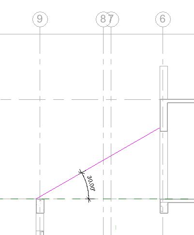
Create a U-shaped monolithic (concrete) staircase in the sample project between “00 Ground Level” to “01 First Floor level” as shown below:

M2 Stair Tutorial 1

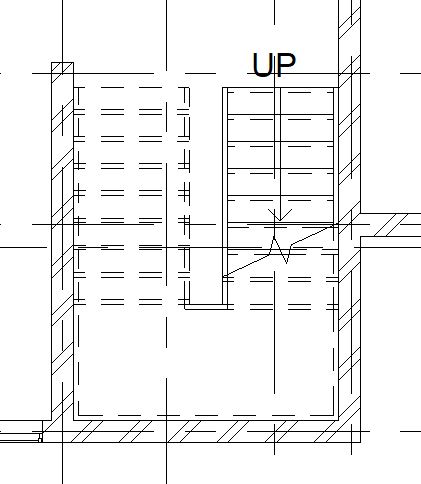
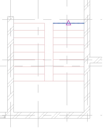
Fig 1. Layout of the U-shaped stairs for the sample project

M2 Stair Tutorial.JPG

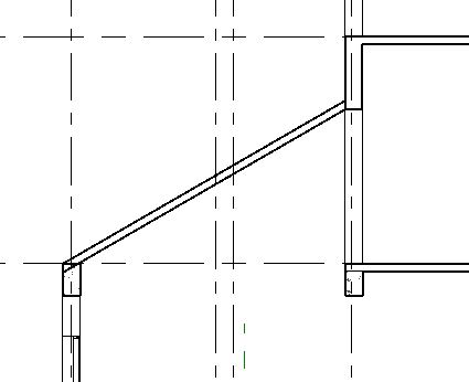
Fig 2. Section view of the U-shaped stairs for the sample project

Sample Files required for this tutorial:

If you do not have the following files, please download them from here.

  • “TutorialStairs_Input_LearningRevitOnline.rvt”

Solution:

Although, Revit provides great tools to automatically calculate number of risers needed for a stair between two selected levels, it makes it easier if you are clear about what kind of stair do you really want for your design. Some planning and preparation goes a long way in making a perfect stair! I recommend that before you begin adding a stair in your project, use “Detail Lines” to sketch out the basic shape of your stair, number of risers you would like to have on each run, overall width of your stair, tread depth and the total height of the stair (between levels/other). 

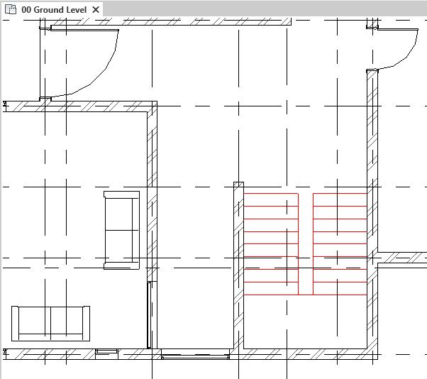
  1. The tutorial file “TutorialStairs_Input_LearningRevitOnline.rvt” already contains the sketch of the stairs using Detail Lines for your reference. Open this file in Revit.
  2. Navigate to the floor plan of “00 Ground Level”. Notice the detail lines marking the basic sketch of the stair. M2 Stair 1
  3. Now, let’s create a U-shaped monolithic stair (RCC/Concrete stair) between Ground Level and First Floor Level by sketching Run component.
  4. To add a stair using Run Component:

    • Click Architecture tab -> Circulation panel -> Stair
    • On the Component panel, verify that Run is selected.
    • On the Options Bar, For Location Line, choose the Run:Center
    • On the Options Bar, add Actual Run width as “1.2m”.
    • Now, in the Type selector, choose Cast-In-Place monolithic stair. 
    • Select the Base level of the stair as “00 Ground Level” and Top level of the stair as “01 First Floor level”. M2 Stair 2
    • Add desired number of risers as 18  and actual tread depth as 0.28m 
    • Notice that when you change the ‘Desired number of Risers’, the actual riser height is calculated automatically by dividing the total stair height/desired number of risers. If this value exceeds the maximum riser height specified in the  type properties, Revit will give an error. Set up your calculation rules in the type properties for maximum riser height and minimum tread depth to prevent the stair risers to be too high and treads to be too narrow while drawing the stair.
    • Go to the Type properties of the stairs and additionally, set up the Run Type and Landing Type as per your design requirements. M2 Stair 3
    • Now, in the drawing area, click to enter the start point of the Run. Choose the starting point as the midpoint of the detail line already sketched, as shown below.M2 Stair 4
    • Move straight downwards to select the endpoint of this first Run as shown below. Notice that as you move your cursor downwards, total number of risers created and remaining are displayed in halftone for your reference.M2 Stair 5
    • The first Run with 9 risers is now created. 
    • Do not worry about the landing at this moment. Continue to draw the second Run by clicking on the starting and ending point as shown below: M2 Stair 6
    • Both Runs are now created and Revit will display that 18 risers are created and 0 are remaining. Notice that the landing has been created automatically by Revit between two Runs. Width of the landing will be the same as the width of the Run.
    • Click on one of the Runs to select it. In the properties palette, note the parameters begins with riser and ends with riser. Make sure both check boxes are on for both runs. We will discuss about these parameters further in Step 7.M2 Stair 12
    • Click on Finish Edit Mode to complete the stairs. M2 Stair 7
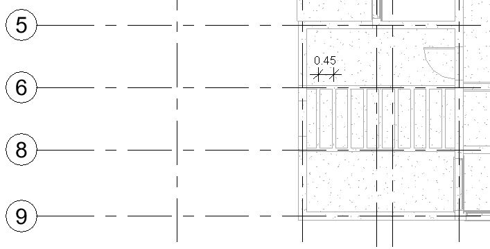
    • The stairs is now added. Notice the annotations of the staircase that have been added automatically by Revit.M2 Stair 9
    • The railing on both sides of the Run and landing has been added automatically. You can select the railing individually and remove it or change its type from the type selector. 
  5.  Now, you may delete all the detail lines that you initially created for reference. 
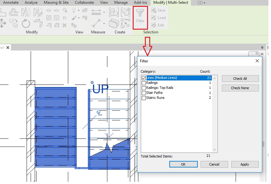
    • TIP: To quickly select all the lines, select all elements in that particular region and then filter selection for the Detail lines.M2 Stair 8
  6. Create a section line to see the stairs in a Section view.
  7. Begin with riser and End with riser:

    • Notice that as we had selected “Begin with riser and end with riser” parameters for both runs, the stairs is sketched accordingly. It is clearer to notice this in a section view. A small gap that you notice between the last riser and the top level, is for the tread thickness. 
      • TIP: If you want to end with a riser but do not want the riser to show up like this, you can select the stair -> Go to Edit Stair -> Select the run and uncheck the box besides “End with Riser” parameter. This will reduce one riser from total number of actual risers. Graphically, this will solve the problem. However, it will display that one riser is less from the overall desired number of risers.M2 Stair 14
      • If you want to begin with a riser but end the stair with a tread, then you have to edit the stair, un-check the ‘End with Riser’ box for the run -> In the layout, drag/extend the run length to include the additional tread & riser in the stair layout. This will ensure that you have included all the desired number of risers.

        M2 Stair 15M2 Stair 16

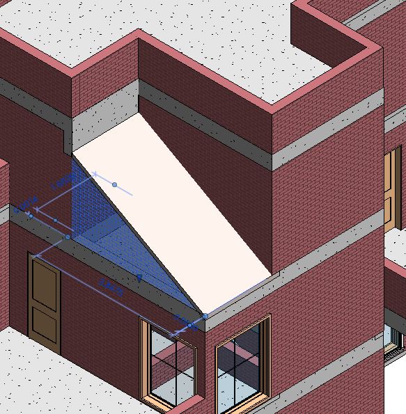
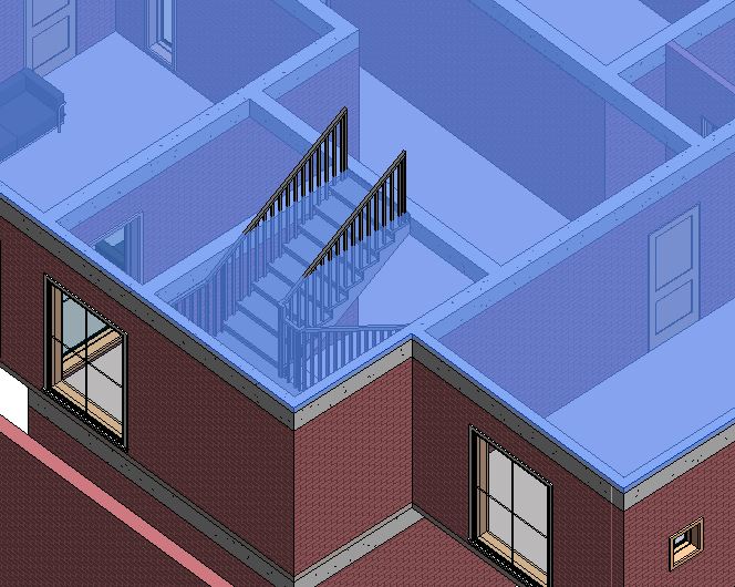
  8. Go to a 3D view to see the stairs in 3D. Notice that an opening is required in the floor slab for the stairs.M2 Stair 13
  9. To create an opening in the floor slab:

    • Select the floor slab for which an opening is needed.
    • Go to Modify|Floors tab -> Mode tab -> Edit Boundary
    • Go to the floor plan where the floor slab is sketched. (for this case, go to ” 01 First Floor Level” floor plan).
    • Draw a closed loop for the opening boundary. Make sure that the boundary for the opening does not intersect or overlap the floor boundary.
      • NOTE: A closed loop inside another closed loop in a sketch mode, will create a void in a solid. 
    • Go to Mode panel -> Finish Edit Mode.M2 Stair 17
    • An opening in the floor slab is created. Go to a 3D view or a section view to see the changes clearly.M2 Stair 18M2 Stair 19.JPG
  10. After completing all the steps, save the project as, “TutorialStairs_Output_LearningRevitOnline.rvt”  

More about Stairs: