About Beam System
Beam system is a tool to add additional support to the main structural frame in the form of cross-beams. You use beam systems to fill structural bays with beams to help support floors or ceilings in a structural model. Beam systems are also useful for laying out rafters for wooden roofs.Tutorial Objective:
It is recommended that you familiarize yourself with Modeling Beams before starting this tutorial.- In this tutorial, you will learn to create a beam system.
Sample Problem:
Create a beam system as shown below in the Fig 1 and Fig 2, in the sample tutorial project.- Beam size = 100mm width x 200mm depth
- Placement of beams at 0.45m spacing from the center.
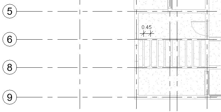
Fig 1. Cross beams (Pergola frames) in the sample tutorial project

Fig 2. Cross beams (pergola frame) in the sample tutorial project
- “TutorialBeamSystem_Input_LearningRevitOnline.rvt”
Solution:
- The tutorial file “TutorialBeamSystem_Input_LearningRevitOnline.rvt” already contains basic model of the building.
- Navigate to the floor plan of “02 Second Floor Level”.
- Before we create a beam system, we must first define the beams on its boundary.
- Create a new type (by duplicating an existing type) of concrete beam of the size 100mm width and 200mm depth.

- Place beams at Grid 6 and 8 at “02 Second Floor Level” elevation with its length extending from Grid B to E, as shown below. (To know more about how to place beams, please refer the tutorial Modeling Beams )

- Now, we have two 100x200mm beams on the longer boundary of the beam system. The wall on Grid B and the existing beam on Grid E shall act as the shorter boundary of the beam system.
-
To add a beam system:
- Go to Structure tab -> Structure panel-> Beam System
- Select Sketch System (from the Modify|Place structural beam system tab-> Beam system panel).
- In the draw panel, select the Boundary Line and Pick Supports option.
- In the drawing area, select the three beams as shown below.

- From the draw panel, select the Pick Lines option.
- In the drawing area, select the inner face of the wall on Grid B as shown below.

- Use Trim/Extend Single Element tool to trim all the sketch lines in a closed loop as shown in the above image.
- From the Draw panel, select the Beam Direction tool. Select one of the shorter sides of the boundary to define the direction of beams to be placed in the beam system.

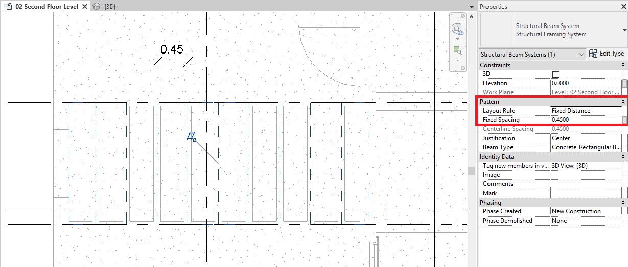
- From the properties palette, define the layout rule of the beams. For this tutorial, choose Fixed Distance from the layout rule.
- Define the distance in the Fixed Spacing parameter as 0.45m (450mm)
- Choose the Justification as Center.
- From the Mode panel -> Click Finish Edit Mode.
- A Beam system has been placed.
- TIP: If you would like to edit layout rule, you can select the beam system and adjust its properties in the properties palette. If you would like to edit the boundary of the beam system, then select the beam system -> Under Modify|Structural Beam system tab -> Mode panel -> click on Edit Boundary.
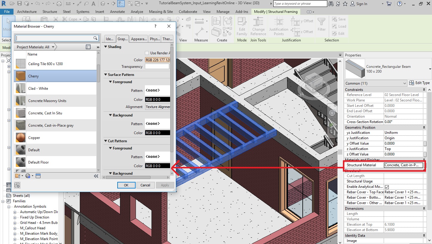
- Go to a 3D view to see the beam system clearly.

- If you would like to change the material of the beams, select one of the beams of 100x200mm type -> Right click and select “Select all Instances -> In Entire Project”. Alternatively, you can also use a keyboard shortcut “SA” to select all instances of the same type in the entire project. After selecting all the beams for which you would like to change the material, go to the properties palette and choose the material you would like to apply.

- After completing all of the steps above, save as the project as, “TutorialBeamSystem_Output_LearningRevitOnline.rvt”
More about Beam Systems:
- Video Tutorial by Autodesk: Place Beam Systems and Structural Floors
- Create an Automatic Beam System
- Modify the Layout of a Beam System

One thought on “Tutorial: Beam system”