Tutorial: Grids

About Grids

Grids are Datum elements used for marking the alignment for the structural elements (columns/structural walls) in a building design. Grids consist of Grid line and Grid symbol. Grid lines can be controlled from Grid properties. Grid symbols can be customized by creating a custom Grid head family.

Tutorial Objective:

In this tutorial, you will learn to,

Sample Problem:

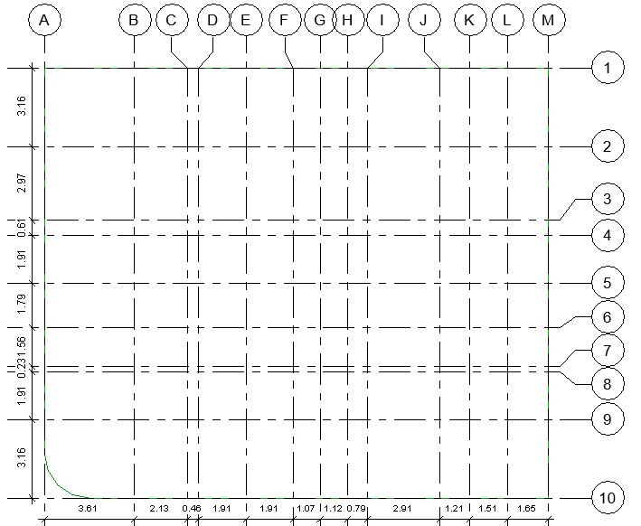
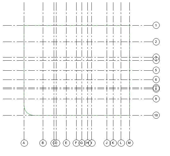
Add Grids in the sample tutorial project as shown below:

  • Vertical Grids from A-M at distances shown in Fig 1.
  • Horizontal Grids from 1-10 at distances shown in Fig 1.

Sample File required for this tutorial: “TutorialGrids_Input_LearningRevitOnline.rvt” (If you do not have this file, please download it from here.)

M2 Grid 6
Fig 1. Grids for the tutorial sample project

Solution:

  1. Open the tutorial file TutorialGrids_Input_LearningRevitOnline.rvt in Revit. This project file already contains the site boundary line created in previous chapter Sketch Lines.M2 Lines 6
  2. From the Project Browser, navigate to the Floor plan view named “00 Ground Level”.
  3. Add a new Grid:

    • Go to Architecture tab -> Datum panel -> Grid
      • Alternatively, use “GR”as the keyboard shortcut.
    • Click Modify | Place Grid tab -> Draw panel -> Select a straight line option.
    • Let’s start by drawing Grid A as shown in Fig 1. Grid A is located at the left vertical boundary line of the site.
    • Click the start point of the Grid at the top left intersection of the site boundary lines in the project.M2 Grid 2
    • Move the cursor downwards vertically. Click to enter Grid end point where you want the Grid line to end.M2 Grid 7
    • Click Esc twice to end the Grid tool.
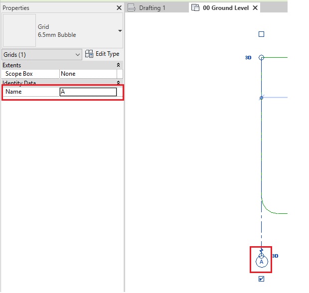
  4. Select the Grid line.
  5. In the Grid symbol, click on the text to change the Grid name from 1 to A. Alternatively, go to properties of the Grid line and in the Instance parameter Name, change the value from 1 to A. M2 Grid 8
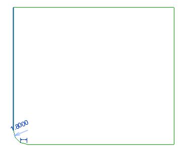
  6. While the Grid line is selected, you may notice the two node like circles at both start and end point. Clicking and dragging these nodes, you can extend the Grid lines. Click and drag the node symbol of the Grid A and extend the grid line away from the site boundary lines.M2 Grid 9
  7. Click Esc to deselect the Grid.
  8. Now, let’s create Grid B as shown in Fig 1. Grid B is located at 3.61m away from Grid A. The best way to create this Grid is to offset Grid A at the specified distance.
  9. Offset a Grid:

    • Go to Architecture tab -> Datum panel -> Grid
      • Alternatively, use “GR”as the keyboard shortcut.
    • Click Modify | Place Grid tab -> Draw panel -> Select Pick Lines tool.
    • On the options bar, specify offset value as 3.61mM2 Grid 10
    • Hover your cursor on Grid A. Revit will show you a dashed blue reference line where the offset will be placed. Click if the position shown by the reference line is correct.
      • TIP: Hover slightly towards right of Grid A to guide Revit to offset towards right side. Similarly, hover your mouse slightly towards left to guide Revit to offset towards left side. The direction will be indicated with a dashed blue reference line showing the position where offset will be placed.
  10. Grid B is added in the drawing. The length of the Grid line is exactly the same as the Grid A as we have used offset tool.
    • Note that the Grid has automatically taken the name “B”. In Revit, Grid numbers are given automatically based on the last number of the Grid that you have specified. However, if you change the value of the grid after it is placed, other already placed grids do not change their value automatically. The change only affects the new Grids.
  11. Using the Pick Lines and Offset method shown in step 9, add Grids C to M with specified distances as shown in Fig 1.M2 Grid 12
  12. All Vertical Grids are added in the project.
    • Tip: If more than one grid lines are already aligned with each other, a small lock sign will be displayed. When the alignment is locked between these Grids, extending one Grid line would automatically extend all other grid lines that are aligned with it. Try to extend the vertical grid lines from A to M as they are already locked in alignment with each other, if you extend one grid line, all other grid lines would also be extended together.
  13. Let’s create Horizontal Grids now.
  14. Add a new Grid:

    • Go to Architecture tab -> Datum panel -> Grid
      • Alternatively, use “GR”as the keyboard shortcut.
    • Click Modify | Place Grid tab -> Draw panel -> Select a straight line option.
    • Grid 1, as per Fig 1, is located at the Top Horizontal boundary line of the site.
    • Click the Start point of the Grid line at the top left intersection of the boundary lines. Move the cursor in horizontal direction and Click the End point of the Grid line where you want the line to end.M2 Grid 13
    • Click Esc twice to end the Grid tool.
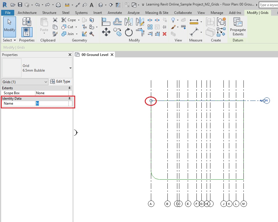
  15. A new horizontal grid has been added and is automatically named as Grid N as the numbering continues from the last Grid line name.
  16. Select the Grid N. Go to its properties and change the Name from N to 1. Press Enter. Alternatively, you can also click on the text inside the Grid symbol and change the value from N to 1.
  17. Click and drag the node like circle on the start point of the Grid 1 and extend the grid line away from the site boundary lines.
  18. To create other Grids at a specified distance from Grid 1, one approach would be to use the Pick Lines and Offset method shown in step 9. The other approach would be to use Copy tool. Let’s create Grid 2 to 10 using the Copy tool.
  19. Select the Grid 1.
  20. Copy Grids:

    • Go to Modify | Grids tab -> Modify Panel -> Copy
    • On the options bar, select Multiple as we want to create multiple copies of Grid 1.
    • On the options bar, select Constraint as we want to constraint the direction of copy downwards (similar to ORTHO ON feature in CAD). M2 Grid 14
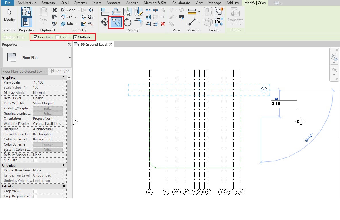
    • Click anywhere on the Grid 1 to establish it as a base point for the copy.
    • Move your cursor downwards. A listening dimension in blue appears. Do not click anywhere yet.
    • Type the specified value between Grid 1 and Grid 2 as per Fig 1  (3.16m).
    • Note that a new Grid is created. Even though, we copied Grid 1, the name of the copied Grid is given automatically as “2” as per the sequence. In Revit, Grids cannot have duplicate names. Each Grid must have a unique name.
    • As multiple option was selected, the Copy tool is still active and more copies can be created by moving the cursor in the direction of copy and specifying the required distance. Using this method, create Grid 3 to 10 as per Fig 1.
    •  Click Esc twice to end the Copy tool.
  21. All horizontal and vertical Grid lines are added in the project.M2 Grid 15
  22. Add Grid symbols to both sides:

    • Note that by default, Grid symbols are appearing on the Grid lines only at one side. If you want to add the Grid symbols on both/either side, select one of the Grid lines.
    • Go to properties palette -> Edit Type -> Type properties dialog -> Plan View Symbols End 1/ End 2 parameters are displayed.
    • Click on Duplicate to duplicate the type and rename it.
      • TIP: Making a change in Type parameter will affect all Instances of the same type present in the entire project. If you do not want this change to affect all instances, then it is recommended that when you make changes to a type parameter, create a new type by duplicate the existing type and renaming it. This way, both the original and the new types are preserved and you can switch between both if necessary / choose which instances shall be affected by the change.
    • Check both parameters to make the grid symbols appear at both sides. (Checking only one of them would make them appear at one of the sides.)M2 Grid 3
    • Click OK after making the change.
    • The selected Grid will now have Grid symbols on both sides.
    • Select all other Grids that you would like to have the same change.
    • Go to Type Selector and change their type to the new type that you just created.M2 Grid 17
  23. Offset Grid Symbols: 

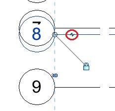
    • Note that on a scale of 1:100, some Grids such as Grid 7 & 8, Grid C & D have Grid symbols that are overlapping each other. For presentation purposes, this requires adjustments.
    • Select Grid 8. Note that there is a small Elbow drag control near the Grid symbol.  Click on this symbol and then drag the control to the desired location to move the bubble away from the grid line.M2 Grid 18.JPG
    •  Do the same for Grid 7 and 9 if required.M2 Grid 19
    • Click Esc to deselect the Grid lines.
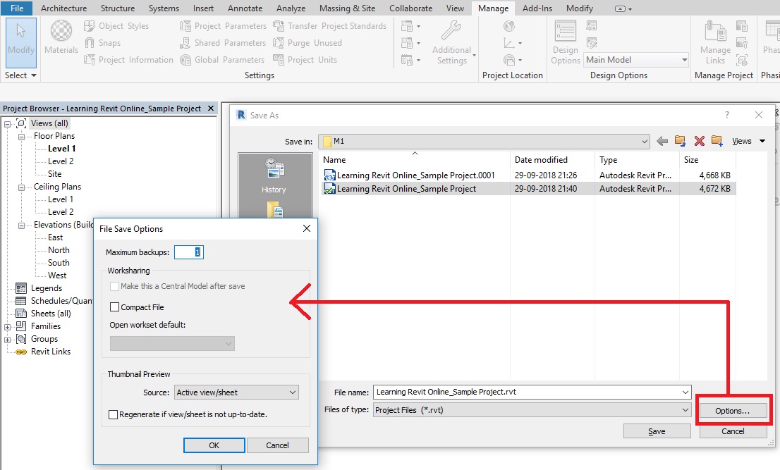
  24. After completing all of the above steps, Go to File -> Save As this project as “TutorialGrids_Output_LearningRevitOnline.rvt”

TIPS:

  • TIP 1 : Custom Grid Symbol: If you want to change the size of the Grid symbol or wish to create a custom design of the Grid symbol, you will need to create a custom Grid Head Family. Learn more about it in this video tutorial by CADuniversity
  • TIP 2: Create Grids from CAD: If you are using a CAD drawing as a reference to draw your Grid lines, you can pick the lines in your CAD drawing to trace and create Revit Grids. Learn more about this method here.
  • TIP 3: Visibility of Grids: If you are unable to see the Grid lines in a particular view, check the visibility factors.
  • TIP 4: Appearance of Grid Line: To change the appearance of the center segment of the grid line, Select the grid line. In the Type Properties dialog, change the value for Center Segment to None or Custom and adjust the properties.

Q&A

Have any Questions? or Suggestions? or Feedback? Please feel free to Contact Us, we will get back to you as soon as we can.

Tutorial: Lines

About Lines

If you are a beginner in Revit or transitioning from CAD tools, lines are the best way to get started. Revit works a bit differently than other popular CAD tools. Thus, getting comfortable in sketching lines would give you a good feel about how the software works.

Many architects like to begin their designs by sketching lines in a layout for space planning. Once an overall single line diagram for the space plan is prepared, the design then moves on to defining walls, columns, grids, etc. In Revit, you can use this approach by starting your project with lines too and then build it up as the design evolves.

There are two types of lines in Revit –

  • Model Lines: Model lines are visible in all views and are mainly used as a reference for the model.
  • Detail Lines: Detail lines are visible only in the specific view it is drawn in and are typically used for annotation in detail drawings.

Tutorial Objective:

In this tutorial, you will learn to,

  • Create Model Lines in the project
  • Create straight line, rectangle and fillet arc lines

Sample Problem:

Sketch the site boundary line of the sample project using model lines as shown below:

  • The overall site boundary dimensions are 20.26m x 17.30m with 1.80m radius arc at the bottom left corner.
M2 Lines Tutorial
Fig 1. Site boundary line for sample tutorial project

Files required for this tutorial: “TutorialLines_Input_LearningRevitOnline.rvt” (If you do not have this file, please download it from here.)

Solution:

  1. Open the sample project file TutorialLines_Input_LearningRevitOnline.rvt
  2. From the Project Browser, navigate to the Floor plan view named “00 Ground Level”.
  3. First, we will begin by drawing site boundary lines as shown in Fig 1 above.
  4. Go to Architecture tab -> Model panel -> Model Line
    • OR type “LI”as a shortcut on the keyboard
  5. In the Modify| Place Lines tab, under the draw panel, you will see options for choosing different shapes to draw. Choose a straight line. Ensure “Chain”option is checked from the options bar.M2 LInes 1
  6. In the drawing area, click to enter line start point in your drawing area.
  7. Move your cursor in a straight horizontal direction.
    •  Revit will highlight tooltips. It will also display dimensions highlighted in blue which change when you move your cursor. They are known as listening dimensions, which gives you relevant references while sketching.
  8. In order to create a line with a specific dimension, type the length of the line (20.26m) from your keyboard. Press Enter. This will determine the end point of the line.M2 Lines 2
  9. As chain option is checked, the line tool is still active allowing you to continue to draw more lines from the last end point.
  10. Move your cursor downwards at 90 degrees to draw a vertical line and type on your keyboard the length of the next line (17.30m). Press Enter.
  11. As we want to create a rectangle, move the cursor in a horizontal direction towards the start point of the first line. This time, Revit will automatically detect the reference for the end point based on the parallel horizontal line that we first drew. It will also highlight the dimension 20.26m, same as we took for the first line. Click at the intersection highlighted. M2 Lines 3
  12. Now, move the cursor upwards in 90 degrees vertical and click at the start point of the first line to close the rectangular loop.
  13. Click Esc twice to end the Model Line tool.
  14. Next, we want to create a fillet arc of 1.8m radius at the bottom left corner of the rectangular site boundary as shown in Fig 1.
  15. Go to Architecture tab -> Model panel -> Model Line
    • OR type “LI”as a shortcut on the keyboard
  16. In the Modify| Place Lines tab, under the draw panel, you will see options for choosing different shapes to draw. Choose a fillet arc. Check the Radius option from the options bar and specify 1.8m as the radius value.M2 Lines 5
  17. Go to the drawing area. Click anywhere on the left vertical line. Next, click on the bottom horizontal line. A fillet arc of 1.8m will be created between these two lines. M2 Lines 6
  18. Click Esc twice to end the Model Line tool.
  19. After completing all of the above steps, Go to File -> Save As this project as “TutorialLines_Output_LearningRevitOnline.rvt

NOTE: As we have created the site boundary line using Model Lines, these lines are also visible in other views including 3D views.

Alternative Approach:

  1. Repeat Steps 1 to 4 from above.
  2. In the Modify| Place Lines tab, under the draw panel, you will see options for choosing different shapes to draw. Choose a rectangle.
  3. In your drawing area, draw a rectangle of an approximate size. Accuracy of the dimensions are not important at this stage.M2 Lines 7
  4. Now, let’s make this rectangle of the exact size as specified in the Fig 1.
    • NOTE: If you click on a vertical line, a horizontal dimension appears in the rectangle and if you select horizontal line, a vertical dimension appears. This might be strange for users who are accustomed to CAD. However, in Revit, the temporary dimensions appear as references to other objects nearby. It understands that if you are selecting a vertical line, you might want to move it either left or right for which you will need the reference of the horizontal dimension. Similarly, for horizontal lines, vertical temporary dimension appears considering that you may want to move the line upwards/downwards.
  5.  Select the left vertical line of the rectangle. Click on the text of the temporary dimension, change its value to 20.26m. Note that the line would move (stretching the rectangle accordingly). Similarly, select the top horizontal line. A vertical temporary dimension will appear between two horizontal lines, change its value to 17.30m and note that the line move accordingly while stretching the rectangle.M2 Lines 4
  6. Now, repeat steps 15 to 19 from the above method, to create a fillet arc at the bottom left corner.

TIPS:

  • TIP: Property Line: As this tutorial is to learn about Model lines, the site boundary has been drawn using Modeling Line tool. However, in reality, it is better to draw site boundary lines using the “Property Line” tool. This will automatically calculate the area of the property enclosed by property lines (which would be a smarter way to do it, right?) Learn more about property line here.
M2 Property Line

More References:

Following are some references from where you can learn more about drawing different shapes with the lines

Q&A

Have any Questions? or Suggestions? or Feedback? Please feel free to Contact Us, we will get back to you as soon as we can.

Tutorial: Levels

About Levels

Use the Level tool to define a vertical height or story within a building. Levels can be added or edited in a vertical view (either elevations or sections).

If you already have information about all the building story levels in your project, you may very well create them before you begin a project. If there are any changes later in the project, you can always come back and make these changes. In case, if you do not have information about all the levels, then it is necessary that you create at least one building story to begin your project. This makes it much easier to attach your walls and other building elements to the levels.

Tutorial Objective

In this tutorial, you will learn to,

Sample Problem:

Define Levels for the sample project as shown below:

  • Ground Level at Elevation Height +/- 00.00
  • Basement Level at Elevation Height -02.71m
  • First Floor Level at Elevation Height +03.05 m
  • Second Floor Level at Elevation Height +06.10m
  • Third Floor Level at Elevation Height +08.84 m

Files required for this tutorial: TutorialLevels_Input_LearningRevitOnline.rvt (If you do not have this file, please download it from here.)

M2 Level Tutorial Sample
Fig 1. Levels for the sample tutorial project

Solution:

  1. Open the sample project file TutorialLevels_Input_LearningRevitOnline.rvt
  2. From the Project Browser, navigate to an Elevation view.
  3. As the sample file was created from an existing architectural template (as shown in previous chapter Create a project file) two levels are part of the template by default.M2 Levels
  4. Note that Level 1 is at 0.00m elevation height currently. In our sample project, we need the “Ground Level” also at 0.00m. So, in this case, it will be enough just to rename the Level 1 to Ground Level.
    • TIP: Naming Conventions: Level names typically will be reflected in the name of the plan views in your project browser where they are sorted alphabetically. Thus, while naming the levels, it is recommended to use naming conventions that allow an alphabetical sorting order to easily find the levels and corresponding plan views. For example, 00_Ground Level -> 01_First Floor Level -> -01_Basement Level. Some users like to add a prefix of the elevation height of the level to the level name in order to sort them correctly. For example, 00.00 Ground Level -> +03.00 First Floor Level -> -03.00 Basement Level. Of course, these naming conventions will still depend on your project specifications and standards.
    • For this tutorial, we are using the floor numbering as the prefix to the level name in order to sort them correctly in the project browser. Thus, the naming convention will be “00 Ground Level”, “01 First Floor Level”, “-01 Basement Level” etc.
  5. Rename the Level:

    • Click on the Level 1 line. The text of the level symbol will be highlighted as blue indicating that it is now editable.
    • Click on the text ‘Level 1’ and replace the text with “00 Ground Level”.
    • The Confirm Level rename dialog box will appear to confirm if the change in level name should be reflected in all corresponding views also? Say Yes to this message in order for all corresponding views to also have the same name as the level in project browser. M2 Levels 3
    • Notice that the Floor plan view named as Level 1 in the project browser is now named same as the level name.
  6. Now, Level 2 is at 4.00m by default. We would like to have the First Floor Level at Elevation Height +03.05 m. Thus, in this case, we will need to change the name as well as the elevation height of the Level 2.
  7. Repeat step 5 and  change the name of the Level 2 to “01 First Floor Level”.
  8. Change the Elevation Height of the Level:

    • Select the Level 2 line, the elevation height value is highlighted as blue indicating that it is now editable. Click on the value and replace it with 3.05m and press Enter. Note that the level line moves to the specified height. M2 Level 8
  9. Next, let’s create a new level for the Basement  Floor at Elevation Height -02.71m
  10. Create a new level:

    • Go to Architecture tab in the ribbon -> Datum panel -> Level
    • Click to enter start point of the level line. Drag your cursor towards the end of the line and then click to enter the end point of the level line. The elevation height of the level need not be accurate at this point.
      • TIP: Take your cursor towards the start point of the Ground Level line and without clicking hover your cursor downwards. Revit will indicate a reference extension line with a dimension that moves with your cursor. At this point, you do not have to be accurate about the dimension. Just click the start point for your new level line at a random point on that reference extension. Similarly, select the end point of the line by referring to the position of the endpoint for Ground level line. After you have placed the level, you can change the elevation height exactly at specified value.M2 Level 9
    • Level 3 will be created in the drawing.
    • Click Esc twice to end the level tool.
    • As shown in step 5 and 8, change the name of this level line to “-01 Basement Floor Level” and elevation of the level to “-2.71”. M2 Level 10
    • Note that a new floor plan view with this level name is added in the project browser.
  11. Using the process shown in step 10, you can create other required levels in the sample project files. Alternatively, you can also use Copy tool to create other levels as shown below.
  12. Copy a Level:

    • Select the “01 First Floor Level” line.
    • Go to Modify|Levels tab -> Select Copy from Modify panel
      • Alternatively, use “CO” as the keyboard for shortcut
    • Keep the ‘Multiple’ option checked in the options bar to make multiple copies of that selected level.
    • Click on any point on ’01 First Floor Level’ line and move your cursor upwards.
      • A temporary dimension (in blue) will appear. You can either choose to graphically select the point where a copy needs to be placed, or type in the exact distance from the base point where you want to the copy to be placed.
    • Type “3.05”value on your keyboard to specify the exact distance between the two level lines. Press Enter after typing the value. This level will become our Second Floor level for the sample project.M2 Level 11
    • As the multiple option is selected, the Copy tool is still active and you can make more copies by moving your cursor upwards and typing the exact copy distance/graphically clicking a point on the screen where you want the copy to be placed. Use this tool to create one more copy of the level that will become our Third floor level for the sample project.
    • Pres Esc twice to finish the Copy tool.
    • Change the name of the levels and elevation height (using the process as shown in step 5 and 8) as below:
      • Name: “02 Second Floor Level” Elevation Height value: “6.10”
      • Name: “03 Third Floor Level” Elevation Height value: “8.84”
  13. Note that the level symbols of Basement, ground and first floor are blue whereas, second and third floor level line symbols are indicated as black. The difference is that for the second and third floor level lines which were created by copy tool, do not automatically generate a plan view in the project browser. Thus, the level symbol indicated this effect by the colour black. If you would like to create a plan view for this level, then follow the procedure as shown below.
  14. Create a Floor Plan View:

    • Go to View tab -> Create panel -> Plan Views drop-down, and then click on Floor plan.
    • In the New Plan dialog box, Select one or more levels for which you want to create a plan view.
    • Click OK.
  15. Now, after creating floor plan views for all levels, note the project browser. All floor plans are sorted alphabetically in order due to the naming conventions we used in the step 4. M2 Levels 13
  16. After completing all of the above steps save this project file (Go to File -> Save) as “TutorialLevels_Output_LearningRevitOnline.rvt

Tips

  • TIP: Add ± symbol in text: If you want to add plus/minus symbol in the text/name of the level,
    • Open character map from your Windows (Windows Accessories -> System Tools -> Character Map) -> Copy the plus/minus symbol from here -> Go back to Revit
    • Select the level line. Click on the name of level name -> Paste this symbol in the text where required. Click Enter.M2 Levels 1
  • TIP: Offset level symbol: For presentation purposes, sometimes if the level heads are too close to each other, you may require to offset the Level symbol for clarity. Learn the steps how to Offset a Level Line from Its Bubble here.
M2 Levels 4

More References

Q&A

Have any Questions? or Suggestions? or Feedback? Please feel free to Contact Us, we will get back to you as soon as we can.

Sample Project

The tutorials in the course ‘Basic 3D Modeling tools for an Architectural project‘ use a sample architectural project of a residential unit. As this is a beginner course, the sample project chosen here is relatively simpler in form and complexity.

To download the sample project and the tutorial Files: Click Here

Once you are familiar with basic Revit functionalities, you can experiment further with Revit using more complex architectural projects and workflows. You may download additional sample project files from Autodesk HELP page for future references.

NOTE:

To get most out of this course, it is recommended that you practice in Revit alongside the tutorials in order to get a hands-on experience on the tools and techniques that you learn during the course.

For any questions or issues in accessing the tutorial files, please Contact Us.

Set up a project file

Project files in Revit have “.RVT” extensions. To create a RVT file, you may either choose to use an existing project template (RTE) file or start a project with no template file. Template files have pre-defined settings which assist the project to get started faster. For example, project units are predefined, basic families commonly used are pre loaded, materials are preset, etc. If you choose not to use any templates, you will have to start your project by defining all settings and load your required library elements. If you are a beginner, it is recommended that you choose a default template file that is provided along with your software library.

1. Create a new project file with a template

  • Open Revit software.
  • Click on New under the projects (OR go to File Tab -> New -> Projects) and choose an ‘Architectural Template’ from the default list. (You can use any other template of your choice as well, if required.)

(Note: If you do not see a list of templates, click on Browse and go to the Program Data folder on the drive where Revit is installed. For example: C:\ProgramData\Autodesk\RVT 2019\Templates OR Alternatively, check the Autodesk folder under your User profile in the computer %ALLUSERSPROFILE%\Autodesk\RVT 2019\Templates)

M1 New project

2. Set up Project Units

Now, once your project file is open, next step would be to set up project units.

  • Go to Manage tab on the Ribbon -> Setting Panel -> Project Units 
  • In the Project Units dialog box, Under discipline -> select Common
  • Change the Length units to the unit of your choice(Ex: Meters)
  • Select required Rounding values (Ex: 1 decimal place) and Unit symbols to be displayed (Ex: m)M1 Units
  • Click OK for Format dialog box.
  • Click OK for the Project Units dialog box.
  • Units for the length has been successfully changed.

(For further practice: Change the Area, Volume and Angle units to Square Meters, Cubic Meters and Decimal Degrees respectively)

  • Learn more about Setting Up project units with the Video Tutorial by Autodesk 

3. Update Project Information

After setting up project units, add some project information to your project.

  • Go to Manage tab on the Ribbon -> Setting Panel -> Project InformationM1 Project Info
  • Project Information dialog box will appear. Add the details about your project in this dialog box such as Project name, Client name, Project Address, etc.
  • Click OK when you are finished adding required information. If you do not know some of the information at this stage, it is okay. You can come back to this dialog box later and add information when you have it with you.

4. Specify Geographic Location for your project

To set your project to a real world site location,

  • Click Manage tab -> Project Location panel -> Location
  • On the Location Weather and Site dialog box, under Define location by -> choose default city list.
  • Under City, choose the city your project is located at.
    • If you do not find the city in the default list, you can also enter the Latitude and Longitude of the exact project site location.
  • Click OK to the location and weather site dialog box.

5. Set up the North orientation

Learn about setting up the North Orientation for your project with this Video Tutorial – by Autodesk Building Solutions

6. Save the project file

  • Go to File Tab -> Save
  • Give file name and Choose the file type as *.RVT (Ex: Learning Revit Online_Sample Project.rvt)
  • Click Options -> File Save Options dialog box will appear -> Choose the maximum number of backups you would like to have for this file.
    • Every time you will save, a previous version of the file would be saved as a backup till the maximum number of backups specified here is reached. After that, it will keep removing the oldest revisions and add a newer version of the backup file. Each backup file will get a suffix of “000n”(n=number of the backup version) with the project name.  (Ex: Learning Revit Online_Sample Project.0001.rvt)M1 save
  • Click Save. Now, you have successfully created a Revit project file.
  • To know more about File Save Options, click here.

Q&A

Have any Questions? or Suggestions? or Feedback? Please feel free to Contact Us, we will get back to you as soon as we can.