About Levels
Use the Level tool to define a vertical height or story within a building. Levels can be added or edited in a vertical view (either elevations or sections).
If you already have information about all the building story levels in your project, you may very well create them before you begin a project. If there are any changes later in the project, you can always come back and make these changes. In case, if you do not have information about all the levels, then it is necessary that you create at least one building story to begin your project. This makes it much easier to attach your walls and other building elements to the levels.
Tutorial Objective
In this tutorial, you will learn to,
- Rename a Level
- Change the elevation height of a Level
- Create a new Level
- Copy a Level
- Create a floor plan view
Sample Problem:
Define Levels for the sample project as shown below:
- Ground Level at Elevation Height +/- 00.00
- Basement Level at Elevation Height -02.71m
- First Floor Level at Elevation Height +03.05 m
- Second Floor Level at Elevation Height +06.10m
- Third Floor Level at Elevation Height +08.84 m
Files required for this tutorial: TutorialLevels_Input_LearningRevitOnline.rvt (If you do not have this file, please download it from here.)

Solution:
- Open the sample project file TutorialLevels_Input_LearningRevitOnline.rvt
- From the Project Browser, navigate to an Elevation view.
- As the sample file was created from an existing architectural template (as shown in previous chapter Create a project file) two levels are part of the template by default.

- Note that Level 1 is at 0.00m elevation height currently. In our sample project, we need the “Ground Level” also at 0.00m. So, in this case, it will be enough just to rename the Level 1 to Ground Level.
- TIP: Naming Conventions: Level names typically will be reflected in the name of the plan views in your project browser where they are sorted alphabetically. Thus, while naming the levels, it is recommended to use naming conventions that allow an alphabetical sorting order to easily find the levels and corresponding plan views. For example, 00_Ground Level -> 01_First Floor Level -> -01_Basement Level. Some users like to add a prefix of the elevation height of the level to the level name in order to sort them correctly. For example, 00.00 Ground Level -> +03.00 First Floor Level -> -03.00 Basement Level. Of course, these naming conventions will still depend on your project specifications and standards.
- For this tutorial, we are using the floor numbering as the prefix to the level name in order to sort them correctly in the project browser. Thus, the naming convention will be “00 Ground Level”, “01 First Floor Level”, “-01 Basement Level” etc.
Rename the Level:
- Click on the Level 1 line. The text of the level symbol will be highlighted as blue indicating that it is now editable.
- Click on the text ‘Level 1’ and replace the text with “00 Ground Level”.
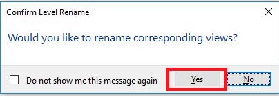
- The Confirm Level rename dialog box will appear to confirm if the change in level name should be reflected in all corresponding views also? Say Yes to this message in order for all corresponding views to also have the same name as the level in project browser.
- Notice that the Floor plan view named as Level 1 in the project browser is now named same as the level name.
- Now, Level 2 is at 4.00m by default. We would like to have the First Floor Level at Elevation Height +03.05 m. Thus, in this case, we will need to change the name as well as the elevation height of the Level 2.
- Repeat step 5 and change the name of the Level 2 to “01 First Floor Level”.
Change the Elevation Height of the Level:
- Select the Level 2 line, the elevation height value is highlighted as blue indicating that it is now editable. Click on the value and replace it with 3.05m and press Enter. Note that the level line moves to the specified height.
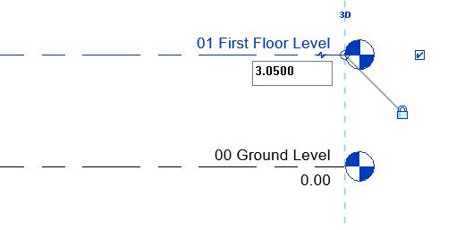
- Select the Level 2 line, the elevation height value is highlighted as blue indicating that it is now editable. Click on the value and replace it with 3.05m and press Enter. Note that the level line moves to the specified height.
- Next, let’s create a new level for the Basement Floor at Elevation Height -02.71m
Create a new level:
- Go to Architecture tab in the ribbon -> Datum panel -> Level
- Click to enter start point of the level line. Drag your cursor towards the end of the line and then click to enter the end point of the level line. The elevation height of the level need not be accurate at this point.
- TIP: Take your cursor towards the start point of the Ground Level line and without clicking hover your cursor downwards. Revit will indicate a reference extension line with a dimension that moves with your cursor. At this point, you do not have to be accurate about the dimension. Just click the start point for your new level line at a random point on that reference extension. Similarly, select the end point of the line by referring to the position of the endpoint for Ground level line. After you have placed the level, you can change the elevation height exactly at specified value.

- TIP: Take your cursor towards the start point of the Ground Level line and without clicking hover your cursor downwards. Revit will indicate a reference extension line with a dimension that moves with your cursor. At this point, you do not have to be accurate about the dimension. Just click the start point for your new level line at a random point on that reference extension. Similarly, select the end point of the line by referring to the position of the endpoint for Ground level line. After you have placed the level, you can change the elevation height exactly at specified value.
- Level 3 will be created in the drawing.
- Click Esc twice to end the level tool.
- As shown in step 5 and 8, change the name of this level line to “-01 Basement Floor Level” and elevation of the level to “-2.71”.

- Note that a new floor plan view with this level name is added in the project browser.
- Using the process shown in step 10, you can create other required levels in the sample project files. Alternatively, you can also use Copy tool to create other levels as shown below.
Copy a Level:
- Select the “01 First Floor Level” line.
- Go to Modify|Levels tab -> Select Copy from Modify panel
- Alternatively, use “CO” as the keyboard for shortcut
- Keep the ‘Multiple’ option checked in the options bar to make multiple copies of that selected level.
- Click on any point on ’01 First Floor Level’ line and move your cursor upwards.
- A temporary dimension (in blue) will appear. You can either choose to graphically select the point where a copy needs to be placed, or type in the exact distance from the base point where you want to the copy to be placed.
- Type “3.05”value on your keyboard to specify the exact distance between the two level lines. Press Enter after typing the value. This level will become our Second Floor level for the sample project.

- As the multiple option is selected, the Copy tool is still active and you can make more copies by moving your cursor upwards and typing the exact copy distance/graphically clicking a point on the screen where you want the copy to be placed. Use this tool to create one more copy of the level that will become our Third floor level for the sample project.
- Pres Esc twice to finish the Copy tool.
- Change the name of the levels and elevation height (using the process as shown in step 5 and 8) as below:
- Name: “02 Second Floor Level” Elevation Height value: “6.10”
- Name: “03 Third Floor Level” Elevation Height value: “8.84”
- Note that the level symbols of Basement, ground and first floor are blue whereas, second and third floor level line symbols are indicated as black. The difference is that for the second and third floor level lines which were created by copy tool, do not automatically generate a plan view in the project browser. Thus, the level symbol indicated this effect by the colour black. If you would like to create a plan view for this level, then follow the procedure as shown below.
Create a Floor Plan View:
- Go to View tab -> Create panel -> Plan Views drop-down, and then click on Floor plan.
- In the New Plan dialog box, Select one or more levels for which you want to create a plan view.
- Click OK.
- Now, after creating floor plan views for all levels, note the project browser. All floor plans are sorted alphabetically in order due to the naming conventions we used in the step 4.

- After completing all of the above steps save this project file (Go to File -> Save) as “TutorialLevels_Output_LearningRevitOnline.rvt“
Tips
- TIP: Add ± symbol in text: If you want to add plus/minus symbol in the text/name of the level,
- Open character map from your Windows (Windows Accessories -> System Tools -> Character Map) -> Copy the plus/minus symbol from here -> Go back to Revit
- Select the level line. Click on the name of level name -> Paste this symbol in the text where required. Click Enter.

- TIP: Offset level symbol: For presentation purposes, sometimes if the level heads are too close to each other, you may require to offset the Level symbol for clarity. Learn the steps how to Offset a Level Line from Its Bubble here.

More References
- Create Levels
- If you are unable to see the level lines in a particular view, check the visibility factors.
- For Revit 2019 and newer versions, level planes can also be visible in 3D views.
- Video Tutorial: Work with Levels in 3D Views by Autodesk
- To customize the level head symbol,
- Video Tutorial: Editing a level symbol by Alexander Vysotskiy
- How to copy levels with Copy tool and array with Array tool.
Q&A
Have any Questions? or Suggestions? or Feedback? Please feel free to Contact Us, we will get back to you as soon as we can.

One thought on “Tutorial: Levels”