About Section Views
Section views cut through the model at a cutting plane specified and show a 2D orthographic projection in the view. Creating section views in a CAD program requires a lot of manual effort. Whereas, in Revit, creating a section view is automated saving significant time and energy. It is as simple as drawing a line to specify the section plane and that’s it! Because the modeled elements in Revit are 3D, the software is able to create their 2D projection along the specified plane automatically. If any building elements are revised, added or removed in the building model, the changes are also reflected in the section views automatically – saving a lot of time, money and energy in coordination of all drawings.
Tutorial Objective:
In this tutorial, you will learn,
- To add a section view
- To rename the section view
- Adjust Crop Boundary and Far Clip Offset of a section view
- Visibility / Graphics: Turn on/off elements in a section view
- Visibility / Graphics: Adjust Project/Cut display of elements in a view
- To break a section line
- To split segment of a section line
Sample Problem:
- Create a vertical section with a split segment
- Create a horizontal section with a break line
- Hide Grid lines from the section view
- Hide surface pattern of the wall in the section view


File required for this tutorial:
“TutorialSectionView_Input_LearningRevitOnline.rvt” (If you do not have this file, please download it from here.)
Solution:
- Open tutorial file “TutorialSectionView_Input_LearningRevitOnline.rvt” in Revit. This project file already contains levels, grids and walls in the basement floor level.
- Navigate to the floor plan of “-01 Basement Floor Level”.
- Now, let’s create a vertical section line as shown in Fig 1.
Add a section View:
- Click View tab -> Create panel -> Section
- From the Type selector, select ‘Building Section’ type.
- In the drawing area, place the cursor at the starting point of the section, and drag through the model. Click when you reach the end point of the section.
- The section line has been created.
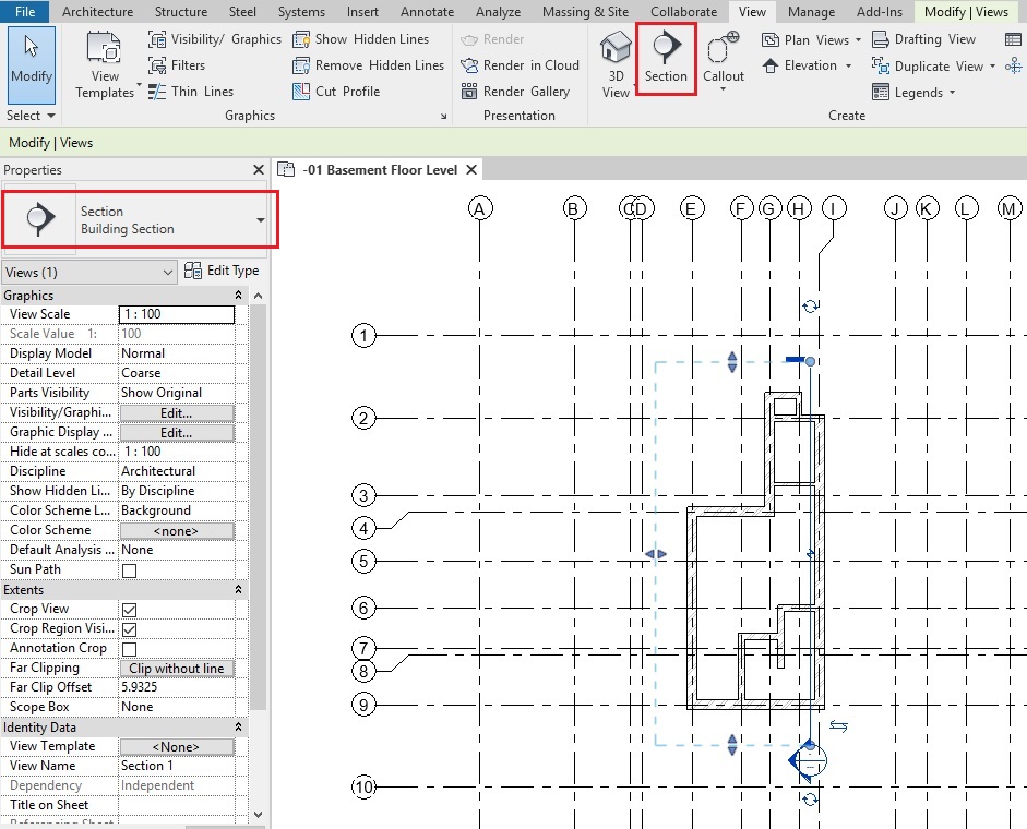
- Click Esc to end the section tool.
- TIP: Click on the section line -> Click on the Flip arrow beside the section head to flip the direction of the section view.
- Double Click on the section head (the blue bubble like symbol), to go to the section view.
- Alternatively, click on the section line -> right click -> Go to View
- Alternatively, navigate to the project browser -> Under Sections -> Double click on the name of the section view to open it.

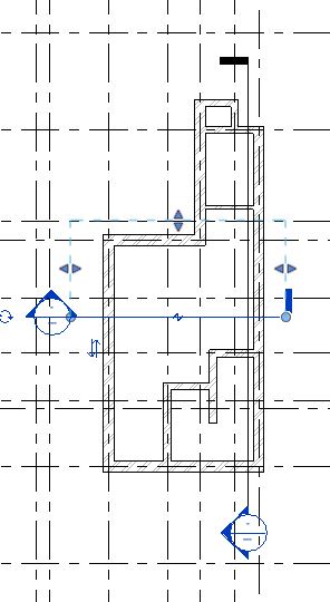
- When you open the section view, you will notice that building elements are shown as cut from the section line that you drew in the layout.
To rename the section view:
- Go to the project Browser -> Right click on the section view you would like rename -> On the right click menu, go to Rename -> Change the name of the view and press Enter.
- Alternatively, click on the section line in the drawing area -> Go to properties -> Under Identity Data -> View Name parameter -> Change the name of the view and press Enter.

- Alternatively, click on the section line in the drawing area -> Go to properties -> Under Identity Data -> View Name parameter -> Change the name of the view and press Enter.
- Go to the project Browser -> Right click on the section view you would like rename -> On the right click menu, go to Rename -> Change the name of the view and press Enter.
- Using the Crop and Far Clip Offset, you can adjust which elements are included in your section view and which are excluded from it. Use the following procedure to adjust the width (crop) and the depth(far clipping) of a section view.
Adjust Crop Boundary and Far Clip Offset of a section view:
- Navigate to the floor plan of “-01 Basement Floor Level”.
- Click on the section line that you added in step 3.
- Notice a blue dotted line in front and on sides of the section line.

- The dotted line in front and parallel to the section line is the far clip offset plane which control the depth of the view. Only those elements are displayed in the view which are within the boundary line of far clip offset plane. Use the blue arrows to adjust the boundary.
- The dotted lines on sides control the crop region (width) of the section view. Only those elements are displayed in the view which are within the boundary line of crop region. Use the blue arrows to adjust the boundary.
- You can also adjust these parameters from the properties of the section line. Click on the section line -> Go to Properties -> Under Extents -> Notice the Crop and Far Clip Offset settings.

- To control the display of elements when they are cut at the far clip plane, adjust the Far Clipping options. Learn more about this Setting here.
- Adjust the Far clip plane and Crop boundary of the section view and then go to the section view to see how the impact of those adjustments.
- To control which elements to display and which to turn off in a view, use Visibility Graphics Settings.
Turn on/off elements in a section view:
- Visibility Graphics allow you to hide/show element categories in a specific view. For example, let’s say that we want to turn off all the Grid lines from the section view.
- Open a Section view from the project browser.
- Go to View Tab -> Graphics panel -> Visibility / Graphics
- Alternatively, use keyboard shortcut “VG”.
- A list of all Revit categories are displayed.
- As Grids are annotation elements. Go to Annotation Categories tab. Scroll down from the list of categories to find Grids. There is a checkbox besides the Grids category. Turn it off.

- Say OK.
- Note that all Grid lines in the view are hidden now.
- To turn them back on, go back to Visibility /Graphics and turn the checkbox on besides the Grid category.
- Visibility/Graphics settings can also be used to control how elements are displayed when in a projection and cut in a section.
Adjust Project/Cut display of elements in a view:
- Let’s say that we want to turn off surface patterns of walls that are displayed in the section view as shown in the image below.

- Go to View Tab -> Graphics panel -> Visibility / Graphics
- Alternatively, use keyboard shortcut “VG”.
- A list of all Revit categories are displayed. As Walls are model elements, go to Model Categories list and scroll down to Walls category.
- Under Project/Surface -> Patterns -> Click on Override -> Turn off the Foreground pattern by switching off the Visible checkbox.

- Click OK to Fill pattern Graphics dialog box.
- Click OK to Visibility / Graphics Override dialog box.
- Note the change in the section view. The brick pattern of the walls shown in projection are turned off.

- Let’s say that we want to turn off surface patterns of walls that are displayed in the section view as shown in the image below.
- Go back to the floor plan of “-01 Basement Floor Level”. Repeat step 4 to add a horizontal section as shown in Fig 1. By default, the name of the section view will be “Section 2”, continuing the number sequence from the previous section. Follow Step 6, if you would like to rename the section view. Repeat Step 8, to adjust the far clip offset and crop boundaries as shown in the image below.
- Sometimes for presentation purposes, you may not want the section line to appear across the entire drawing. In this case, the section line is required to be displayed as broken lines instead of one continuous line.
To break a section line:
- Click the section line of Section 2 (section line you created in step 13).
- Notice the break control symbol on the line.
- Click on the break control symbol to break the section line.
- The section break is in the middle of the section line. The following images show the same section, whole and broken.


- To rejoin the section line, click the break control again.
- A break in a section line is view-specific. It affects the display of the section only in the view where the break was made.
- If you would like to split the cutting plane of the section view in order to show two different areas of the model, you can use ‘split segment’ tool.
To split section line segment:
- Click on the section line of Section 1 (vertical section line created in step 4).
- Go to Modify|Views tab -> Section -> Split Segment
- Click on the section line from where you would like to begin the split.
- Move your cursor in the direction where you would like to position the split segment. Click where you want to place it.
- A section line has been split.
- Click Esc twice to end the Split Segment tool.
- Click on the section line again.
- Using the arrows on the section line, you can adjust the split segments, if necessary.
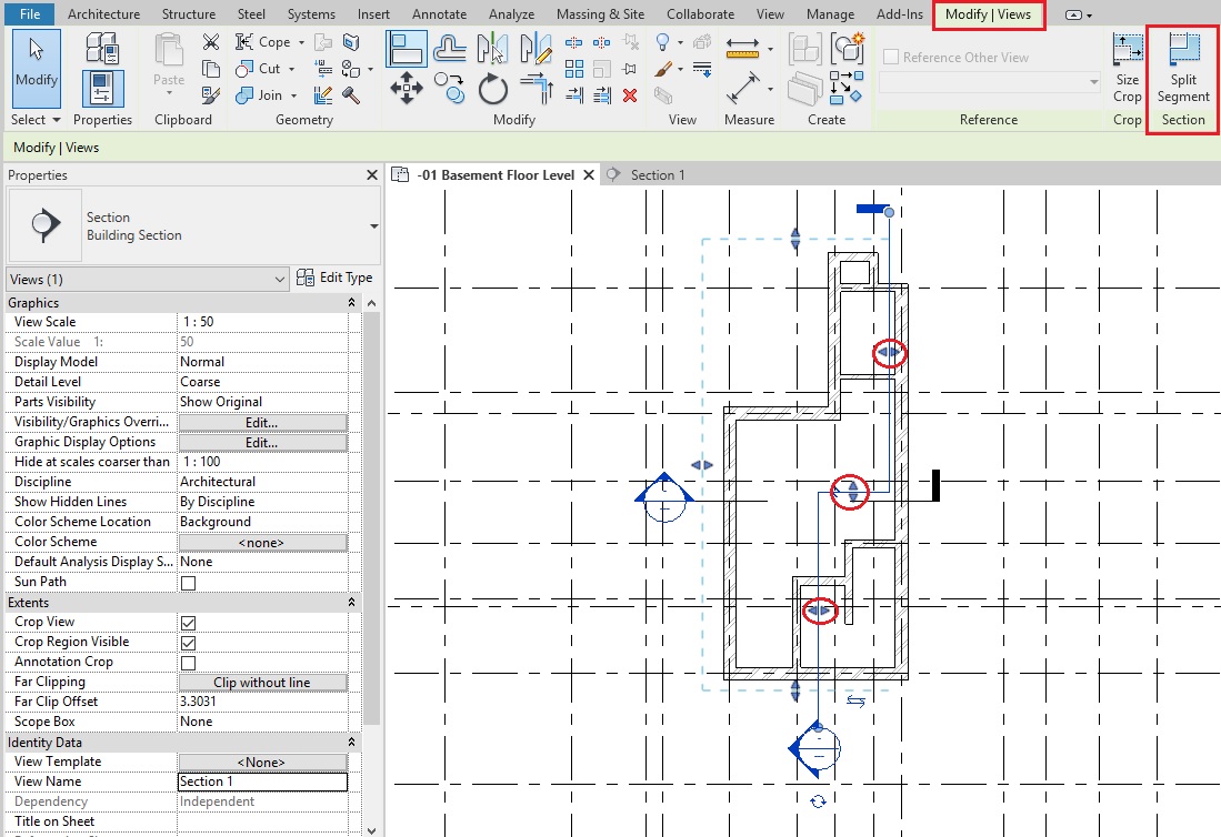
- Go to the view and observe how the view is revised after the split segment.
- After completing all of the above steps, Save As your project as “TutorialSectionView_Output_LearningRevitOnline.rvt”
TIPS
- TIP: Custom Section Tag
The type properties of the section line specifies which section tag to use. The Section tag contains a section head and a section tail. Both, the head and the tail, are symbols that can be selected from the properties of the section tag.
To customize the section tag symbol, a section head family needs to be created and then added to a section tag.
Step 1: How to create a section head family? / Video Tutorial: Create a custom section head family presented by RevitWhisperer
Step 2: How to add the section head family into a section tag?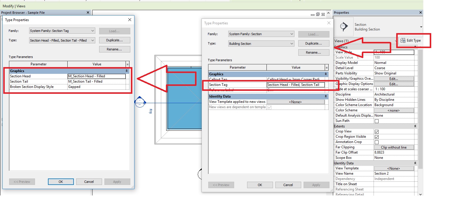
More References
- Learn more about Visibility Graphics and Object Style.
- Learn more about creating Sections.
Q&A
Have any Questions? or Suggestions? or Feedback? Please feel free to Contact Us, we will get back to you as soon as we can.

One thought on “Tutorial: Section Views”